


Intel Desktop Board D925XCV/D925XBC Technical Product Specification
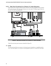
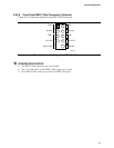
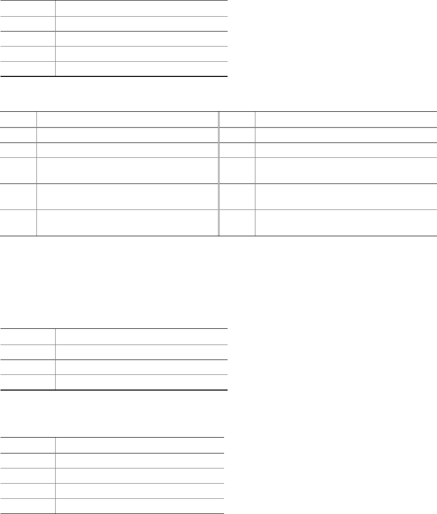
Table 21. ATAPI CD-ROM Connector
Pin Signal Name
1 Left audio input from CD-ROM
2 CD audio differential ground
3 CD audio differential ground
4 Right audio input from CD-ROM
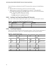
Table 22. Front Panel Audio Connector
Pin Signal Name Pin Signal Name
1 Port E [Port 1] Left Channel 2 Ground
3 Port E [Port 1] Right Channel 4 Presence# (dongle present)
5 Port F [Port 2] Right Channel 6 Port E [Port 1] Sense return
(jack detection)
7 Port E [Port 1] and Port F [Port 2]
Sense send (jack detection)
8 Key
9 Port F [Port 2] Left Channel 10 Port F [Port 2] Sense return
(jack detection)
#
INTEGRATOR’S NOTE
The front panel audio connector is colored yellow.
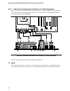
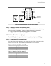
Table 23. Front Chassis Fan and Rear Chassis
Fan Connectors
Pin Signal Name
1 Control
2 +12 V
3 Tach
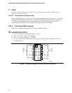
Table 24. Processor Fan Connector and Auxiliary
Rear Fan Connector
Pin Signal Name
1 Ground
2 +12 V
3 FAN_TACH
4 FAN_CONTROL
✏
NOTE
The auxiliary rear fan connector is present only on the D925XCV board. It is not present on the
D925XBC board.
72