


Intel
®
E8500 Chipset North Bridge (NB) and eXternal Memory 15
Bridge (XMB) Thermal/Mechanical Design Guide
3 Thermal Specifications
3.1 Thermal Design Power (TDP)
Analysis indicates that real applications are unlikely to cause the E8500 chipset NB/XMB
components to consume maximum power dissipation for sustained time periods. Therefore, in
order to arrive at a more realistic power level for thermal design purposes, Intel characterizes
power consumption based on known platform benchmark applications. The resulting power
consumption is referred to as the Thermal Design Power (TDP). TDP is the target power level that
the thermal solutions should be designed to. TDP is not the maximum power that the chipset can
dissipate.
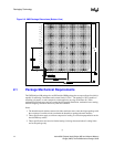
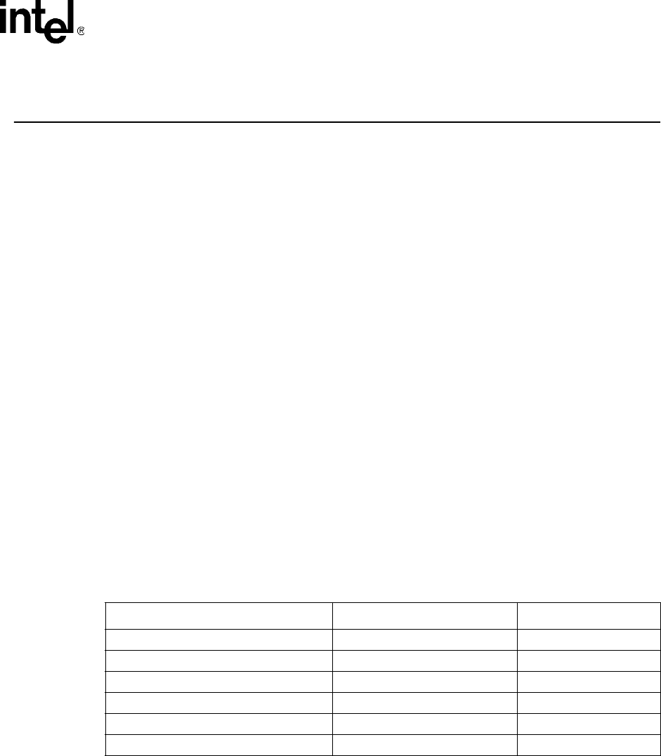
For TDP specifications, see Table 3-1 for the E8500 chipset NB component and Table 3-2 for the
E8500 chipset XMB component FC-BGA packages have poor heat transfer capability into the
board and have minimal thermal capability without a thermal solution. Intel recommends that
system designers plan for one or more heatsinks when using the E8500 chipsets NB/XMB
components.
3.2 Die Case Temperature Specifications
To ensure proper operation and reliability of the E8500 chipset NB/XMB components, the die
temperatures must be at or between the maximum/minimum operating temperature ranges as
specified in Table 3-1 and Table 3-2. System and/or component level thermal solutions are required
to maintain these temperature specifications. Refer to Section 5 for guidelines on accurately
measuring package die temperatures.
NOTE:
1. These specifications are based on silicon characterization, however, they may be updated as further data
becomes available.
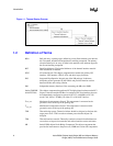
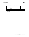
Table 3-1. Intel
®
E8500 Chipset NB Thermal Specifications
Parameter Value Notes
T
case_max
104°C
T
case_min
5°C
TDP
with 1 XMB attached
17.9W
TDP
with 2 XMBs attached
19.8W
TDP
with 3 XMBs attached
22.4W
TDP
with 4 XMBs attached
24.5W