


Intel
®
E8500 Chipset North Bridge (NB) and eXternal Memory 39
Bridge (XMB) Thermal/Mechanical Design Guide
XMB Reference Thermal Solution
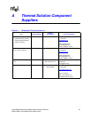
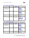
Full mechanical drawings of the thermal solution assembly and the heatsink are provided in
Appendix B. Appendix A contains vendor information for each thermal solution component.
8.5.1 Heatsink Orientation
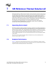
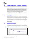
Since this solution is based on a unidirectional heatsink, mean airflow direction must be aligned
with the direction of the heatsink fins.
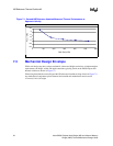
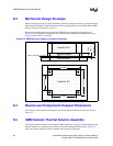
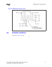
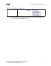
Figure 8-3. XMB Heatsink Board Component Keepout
XMB Location
No Component Keep Out Area
2.48mm Max Component Height
Heatsink Mounting Hole
38.097mm. 48.260mm.
37.500mm.
55.250mm.
63.500mm.
4X Ø 5.5mm
4X Ø 2.95 ± 0.0254mm
37.5mm
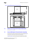
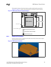
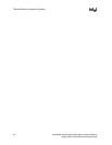
Figure 8-4. XMB Heatsink Assembly