


Intel
®
E8500 Chipset North Bridge (NB) and eXternal Memory 27
Bridge (XMB) Thermal/Mechanical Design Guide
NB Reference Thermal Solution #1
6.5.1 Heatsink Orientation
Since this solution is based on a unidirectional heatsink, mean airflow direction must be aligned
with the direction of the heatsink fins.
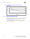
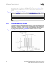
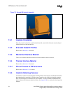
6.5.2 Extruded Heatsink Profiles
The reference NB thermal solution uses an extruded heatsink for cooling the chipset NB.
Figure 6-5 shows the heatsink profile. Appendix A lists a supplier for this extruded heatsink. Other
heatsinks with similar dimensions and increased thermal performance may be available. Full
mechanical drawing of this heatsink is provided in Appendix B.
6.5.3 Mechanical Interface Material
There is no mechanical interface material associated with this reference solution.
6.5.4 Thermal Interface Material
A TIM provides improved conductivity between the die and heatsink. The reference thermal
solution uses Chomerics THERMFLOW* T710, 0.127 mm (0.005 in.) thick, 38.5 mm x 38.5 mm
(1.5 in. x 1.5 in.) square.
Note: Unflowed or “dry” Chomerics THERMFLOW T710 has a material thickness of 0.005 inch.
The flowed or “wet” Chomerics THERMFLOW T710 has a material thickness of ~0.0025 inch
after it reaches its phase change temperature.
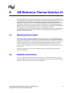
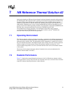
6.5.4.1 Effect of Pressure on TIM Performance
As mechanical pressure increases on the TIM, the thermal resistance of the TIM decreases. This
phenomenon is due to the decrease of the bond line thickness (BLT). BLT is the final settled
thickness of the thermal interface material after installation of heatsink. The effect of pressure on
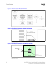
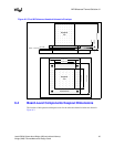
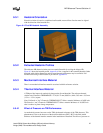
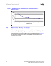
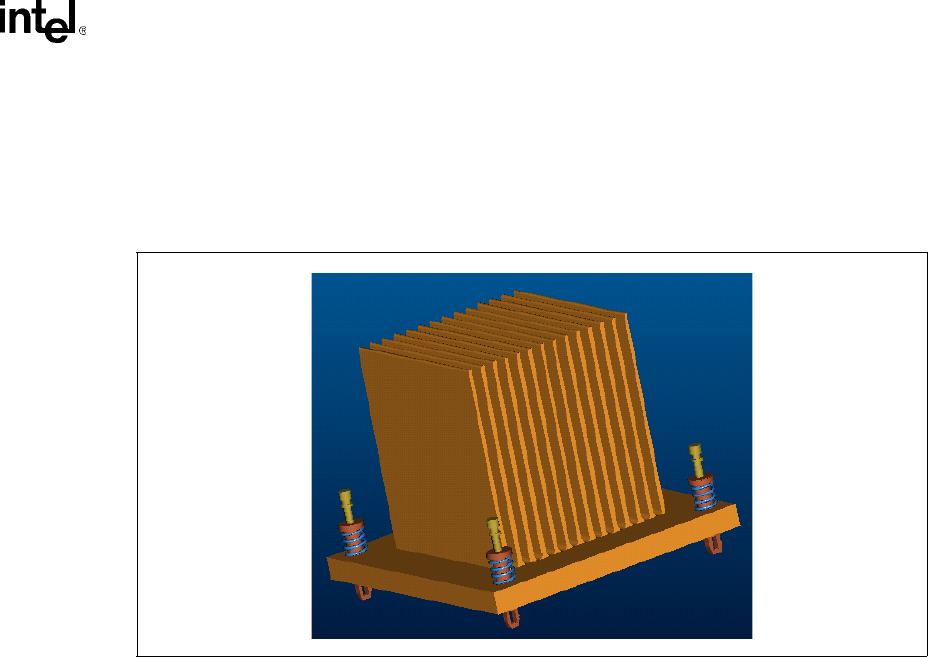
Figure 6-4. First NB Heatsink Assembly