


4 Intel
®
E8500 Chipset North Bridge (NB) and eXternal Memory
Bridge (XMB) Thermal/Mechanical Design Guide
8.5 XMB Heatsink Thermal Solution Assembly....................................................................... 38
8.5.1 Heatsink Orientation ........................................................................................... 39
8.5.2 Extruded Heatsink Profiles ................................................................................. 40
8.5.3 Mechanical Interface Material............................................................................. 40
8.5.4 Thermal Interface Material.................................................................................. 40
8.5.5 Heatsink Retaining Fastener .............................................................................. 40
8.6 Reliability Guidelines......................................................................................................... 41
A Thermal Solution Component Suppliers ..........................................................................43
B Mechanical Drawings .......................................................................................................47
Figures
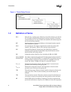
1-1 Thermal Design Process..................................................................................................... 8
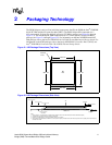
2-1 NB Package Dimensions (Top View) ................................................................................ 11
2-2 NB Package Dimensions (Side View) ............................................................................... 11
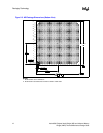
2-3 NB Package Dimensions (Bottom View)........................................................................... 12
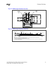
2-4 XMB Package Dimensions (Top View) ............................................................................. 13
2-5 XMB Package Dimensions (Side View) ............................................................................ 13
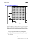
2-6 XMB Package Dimensions (Bottom View)........................................................................ 14
5-1 Thermal Solution Decision Flowchart................................................................................ 20
5-2 Zero Degree Angle Attach Heatsink Modifications............................................................ 20
5-3 Zero Degree Angle Attach Methodology (Top View)......................................................... 20
6-1 First NB Reference Heatsink Measured Thermal Performance vs.
Approach Velocity ............................................................................................................. 24
6-2 First NB Reference Heatsink Volumetric Envelope........................................................... 25
6-3 First NB Heatsink Board Component Keepout.................................................................. 26
6-4 First NB Heatsink Assembly.............................................................................................. 27
6-5 First NB Heatsink Extrusion Profile................................................................................... 28
7-1 Second NB Reference Heatsink Measured Thermal Performance vs.
Approach Velocity ............................................................................................................. 32
7-2 Second NB Reference Heatsink Volumetric Envelope ..................................................... 33
7-3 Second NB Heatsink Assembly ........................................................................................ 34
8-1 XMB Reference Heatsink Measured Thermal Performance vs. Approach Velocity.......... 37
8-2 XMB Reference Heatsink Volumetric Envelope................................................................ 38
8-3 XMB Heatsink Board Component Keepout....................................................................... 39
8-4 XMB Heatsink Assembly................................................................................................... 39
8-5 XMB Heatsink Extrusion Profile ........................................................................................ 41
B-1 NB Heatsink #1 Assembly Drawing .................................................................................. 48
B-2 NB Heatsink #1 Drawing................................................................................................... 49
B-3 NB Heatsink #2 Assembly Drawing .................................................................................. 50
B-4 NB Heatsink #2 Drawing................................................................................................... 51
B-5 XMB Heatsink Assembly Drawing..................................................................................... 52
B-6 XMB Heatsink Drawing ..................................................................................................... 53