


4 ETX® connectors
Kontron User's Guide ETX CD 18
4 ETX® connectors
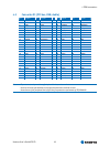
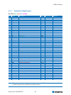
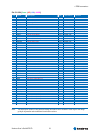
The pinouts for ETX® Interface Connectors X1, X2, X3, and X4 are documented for convenient reference.
Please see the ETX® Specification and ETX® Design Guide for detailed, design-level information.
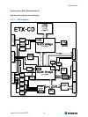
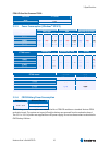
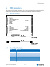
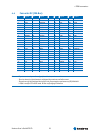
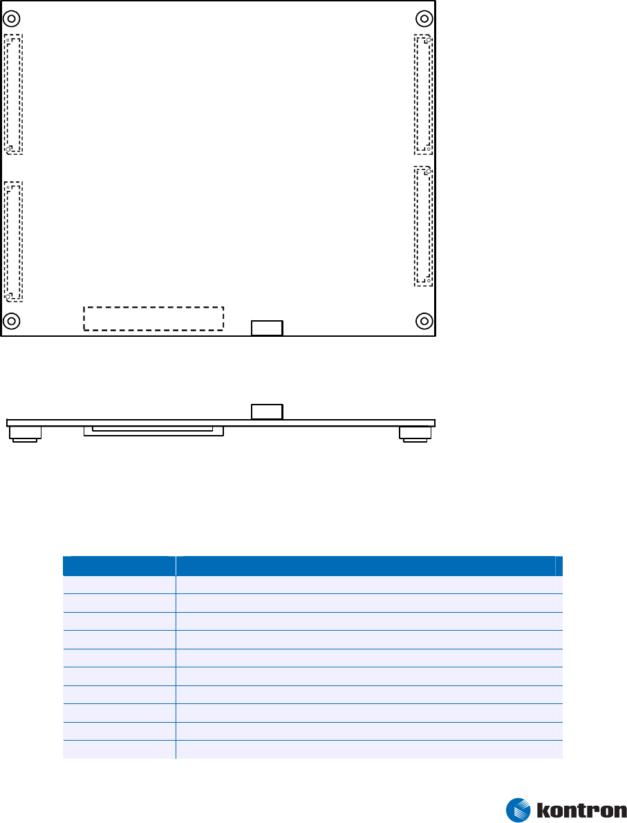
4.1 Connector Locations
IDE Port
Ethernet
Power Good/Reset Input
ATX PS Control
Speaker
Battery
I2C-Bus
SM-Bus
ISA Bus
VGA
LVDS (JILI)
Serial Ports
PS/2 Keyboard/Mouse
IRDA
Parallel Port
Floppy
TV-out
PCI Bus
USB
Audio
Serial IRQ
3.3 V for external use
(max. 500 mA)
side view
(connectors only)
top view
(connectors only)
X
1
X
2X4
X3
Feature Connector J11
SDVO
Fan-connector
4.2 General Signal Description
Term Description
IO-3,3 Bi-directional 3,3 V IO-Signal
IO-5 Bi-directional 5 V IO-Signal
I-3,3 3,3 V Input
I-5 5 V Input
O-3,3 3,3 V Output
O-5 5 V Output
PU Pull-Up Resistor
PD Pull-Down Resistor
PWR Power Connection
Nc Not Connected / Reserved