


4 ETX® connectors
Kontron User's Guide ETX CD 38
➤
45pos,150 mm length, 0.5mm pitch, both ends opposite sides
Connector
➤
Hirose - FH12-45S-0.5SH
➤
0.50mm (.020") Pitch FFC/FPC Connector, Horizontal Right Angle, SMT, 45 Circuits
4.7.3 BIOS Requirements
There is currently no support for this feature!
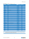
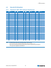
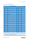
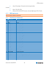
4.7.4 Pinout Feature Connector J11
Pin Pin on ETX®-CD Description
1 GND1 Ground
2 SDVOC_CLKN Channel C; Clock negative
3 SDVOC_CLKN Channel C; Clock positive
4 GND2 Ground
5 SDVOC_GREENN Channel C; Green negative
6 SDVOC_GREENP Channel C; Green positive
7 GND3 Ground
8 SDVOB_CLKN Channel B; Clock negative
9 SDVOB_CLKN Channel B; Clock positive
10 GND4 Ground
11 SDVOB_GREENN Channel B; Green negative
12 SDVOB_GREENP Channel B; Green positive
13 GND5 Ground
14 SDVOC_INTN Channel C; Interrupt negative
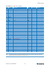
15 SDVOC_IN
T
P Channel C; Interrupt positive
16 GND6 Ground
17 SDVOB_INTN Channel B; Interrupt negative
18 SDVOB_IN
T
P Channel B; Interrupt positive
19 GND7 Ground
20 SDVOC_BLUEN Channel C; Blue negative
21 SDVOC_BLUEP Channel C; Blue positive
22 GND8 Ground
23 SDVOC_REDN Channel C; Red negative
24 SDVOC_REDP Channel C; Red positive
25 GND9 Ground
26 SDVOB_BLUEN Channel B; Blue negative
27 SDVOB_BLUEP Channel B; Blue positive
28 GND10 Ground
29 SDVOB_REDN Channel B; Red negative
30 SDVOB_REDP Channel B; Red positive
31 GND11 Ground
32 SDVO_FLDSTALLN Field Stall negative
33 SDVO_FLDSTALLP Field Stall positive
34 GND12 Ground
35 SDVO_TVCLKINN TV Clock Input negative
36 SDVO_TVCLKINP TV Clock Input positive
37 GND13 Ground
38 SDVO_CTRCLK I2C based control signal for SDVO devices; clock
39 SDVO_CTRLDATA I2C based control signal for SDVO devices; data
40 RESET# Reset signal
41 VCC 5V power
42 VCC 5V power
43 VCC 5V power