


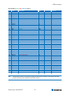

4 ETX® connectors
Kontron User's Guide ETX CD 35
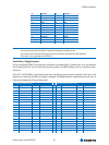
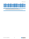
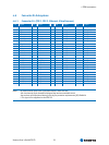
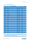
Pin 51-100:
[Power | IDE | Ethernet | Misc ]
Pin Si
g
na
l
Descri
p
tion T
yp
e Termination Commen
t
51 SIDE_IOW# - nc - -
52 PIDE_IOR# Primar
y
IDE IO Read O-3,3 - -
53 SIDE_DRQ - nc - -
54 PIDE_IOW# Primar
y
IDE IO Write O-3,3 - -
55 SIDE_D15 - nc - -
56 PIDE_DRQ Primar
y
IDE DMA Re
q
ues
t
I-3,3 PU 11k5 3,3V -
57 SIDE_D0 - nc - -
58 PIDE_D15 Primar
y
IDE Data Bus IO - -
59 SIDE_D14 - nc - -
60 PIDE_D0 Primar
y
IDE Data Bus IO - -
61 SIDE_D1 - nc - -
62 PIDE_D14 Primar
y
IDE Data Bus IO - -
63 SIDE_D13 - nc - -
64 PIDE_D1 Primar
y
IDE Data Bus IO - -
65 GND Ground PWR - -
66 GND Ground PWR - -
67 SIDE_D2 - nc - -
68 PIDE_D13 Primar
y
IDE Data Bus IO - -
69 SIDE_D12 - nc - -
70 PIDE_D2 Primar
y
IDE Data Bus IO - -
71 SIDE_D3 - nc - -
72 PIDE_D12 Primar
y
IDE Data Bus IO - -
73 SIDE_D11 - nc - -
74 PIDE_D3 Primar
y
IDE Data Bus IO - -
75 SIDE_D4 - nc - -
76 PIDE_D11 Primar
y
IDE Data Bus IO - -
77 SIDE_D10 - nc - -
78 PIDE_D4 Primar
y
IDE Data Bus IO - -
79 SIDE_D5 - nc - -
80 PIDE_D10 Primar
y
IDE Data Bus IO - -
81 VCC Power +5V PWR - -
82 VCC Power +5V PWR - -
83 SIDE_D9 - nc - -
84 PIDE_D5 Primar
y
IDE Data Bus IO - -
85 SIDE_D6 - nc - -
86 PIDE_D9 Primar
y
IDE Data Bus IO - -
87 SIDE_D8 - nc - -
88 PIDE_D6 Primar
y
IDE Data Bus IO - -
89 GPE2# General Pur
p
ose Power Event 1 I-3,3 PU 8k2 3,3V RI of ICH7
90 CBLID_P# 80-conductor IDE cable Channel 0 I-3,3 PD 10k -
91 RXD# Ethernet Receive Differential Si
g
nal
(
RXD-
)
I - 121R between
92 PIDE_D8 Primar
y
IDE Data Bus IO - -
93 RXD Ethernet Receive Differential Si
g
nal
(
RXD+
)
I - 121R between
94 SIDE_D7 - nc - -
95 TXD# Ethernet Transmit Differential Si
g
nal
(
TXD-
)
O - 100R
/
C10
p
between
96 PIDE_D7 Primar
y
IDE Data Bus IO - int. PD 11k5 ICH7-M
97 TXD Ethernet Transmit Di
f
ferential Si
g
nal
(
TXD+
)
O - 100R
/
C10
p
between
98 HDRST# Hard Drive Rese
t
O-5 - -
99 GND Ground PWR - -
100 GND Ground PWR - -
Note: The termination resistors in this table are already mounted on the ETX® board. Please refer to the design
guide for information about additional termination resistors.