


4 ETX® connectors
Kontron User's Guide ETX CD 27
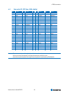
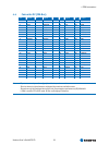
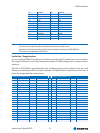
25 LCDDO9 26 LCDDO10
27 GND 28 GND
29 LCDDO4 30 LCDDO7
31 LCDDO5 32 LCDDO6
33 GND 34 GND
35 LCDDO1 36 LCDDO3
37 LCDDO0 38 LCDDO2
39 VCC * 40 VCC *
41 JILI_DAT 42 LTGIO0**
43 JILI_CLK 44 BLON#
45 BIASON** 46 DIGON
47 COMP** 48 Y**
49 SYNC** 50 C**
Notes: *To protect external power lines of peripheral devices, make sure that:
- the wires have the right diameter to withstand the maximum available current
- the enclosure of the peripheral device fulfils the fire-protection requirements of IEC/EN60950.
**This signal is not supported on the ETX®-CD.
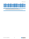
Parallel Port / Floppy Interfaces
You can configure ETX®-CD’s parallel port interfaces as conventional PC parallel ports or as an interface
for a floppy-disk drive. You can select the operating mode in the BIOS settings and by a hardware mode-
select pin.
If Pin X3-51 (LPT/FLPY#) is grounded at boot time, the floppy support mode is selected. If the pin is left
floating or is held high, parallel-port mode is selected. The mode selection is determined at boot time. It
cannot be changed until the next boot cycle.
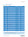
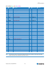
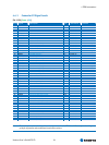
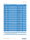
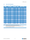
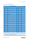
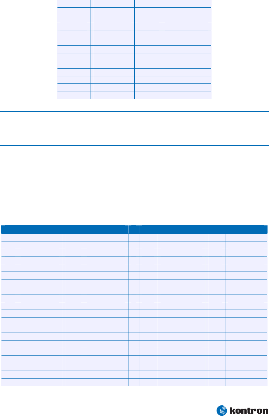
Parallel Port Mode Pinout Floppy Support Mode Pinout
Pin Signal Pin Signal Pin Signal Pin Signal
51 LPT/FLPY# 52 RESERVED 51 LPT/FLPY# 52 RESERVED
53 VCC * 54 GND 53 VCC * 54 GND
55 STB# 56 AFD# 55 RESERVED 56 DENSEL
57 RESERVED 58 PD7 57 RESERVED 58 RESERVED
59 IRRX 60 ERR# 59 IRRX 60 HDSEL#
61 IRTX 62 PD6 61 IRTX 62 RESERVED
63 RXD2 64 INIT# 63 RXD2 64 DIR#
65 GND 66 GND 65 GND 66 GND
67 RTS2# 68 PD5 67 RTS2# 68 RESERVED
69 DTR2# 70 SLIN# 69 DTR2# 70 STEP#
71 DCD2# 72 PD4 71 DCD2# 72 DSKCHG#
73 DSR2# 74 PD3 73 DSR2# 74 RDATA#
75 CTS2# 76 PD2 75 CTS2# 76 WP#
77 TXD2 78 PD1 77 TXD2 78 TRK0#
79 RI2# 80 PD0 79 RI2# 80 INDEX#
81 VCC * 82 VCC* 81 VCC * 82 VCC *
83 RXD1 84 ACK# 83 RXD1 84 DRV
85 RTS1# 86 BUSY 85 RTS1# 86 MOT
87 DTR1# 88 PE 87 DTR1# 88 WDATA#