


33
2 Technical Reference
What This Chapter Contains
2.1 Introduction................................................................................................................ 33
2.2 Memory Map ............................................................................................................. 33
2.3 I/O Map ..................................................................................................................... 34
2.4 DMA Channels .......................................................................................................... 35
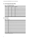
2.5 PCI Configuration Space Map ................................................................................... 36
2.6 Interrupts ...................................................................................................................36
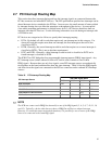
2.7 PCI Interrupt Routing Map......................................................................................... 37
2.8 Connectors................................................................................................................ 38
2.9 Jumper Block............................................................................................................. 49
2.10 Mechanical Considerations........................................................................................ 51
2.11 Electrical Considerations ........................................................................................... 53
2.12 Thermal Considerations............................................................................................. 55
2.13 Reliability ................................................................................................................... 56
2.14 Environmental............................................................................................................ 57
2.15 Regulatory Compliance ............................................................................................. 58
2.1 Introduction
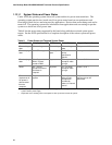
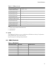
Sections 2.2 – 2.6 contain several standalone tables. Table 11 describes the system memory map,
Table 12 shows the I/O map, Table 13 lists the DMA channels, Table 14 defines the PCI
configuration space map, and Table 15 describes the interrupts. The remaining sections in this
chapter are introduced by text found with their respective section headings.
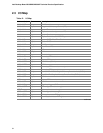
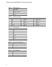
2.2 Memory Map
Table 11. System Memory Map
Address Range (decimal) Address Range (hex) Size Description
1024 K – 262144 K 100000 – FFFFFFF 255 MB Extended memory
960 K – 1024 K F0000 – FFFFF 64 KB Runtime BIOS
896 K – 960 K E0000 – EFFFF 64 KB Reserved
800 K – 896 K C8000 – DFFFF 96 KB Available high DOS memory (open
to PCI bus)
640 K – 800 K A0000 – C7FFF 160 KB Video memory and BIOS
639 K – 640 K 9FC00 – 9FFFF 1 KB Extended BIOS data (movable by
memory manager software)
512 K – 639 K 80000 – 9FBFF 127 KB Extended conventional memory
0 K – 512 K 00000 – 7FFFF 512 K Conventional memory