


Contents
vii
4.5 Security Menu............................................................................................................ 83
4.6 Power Menu .............................................................................................................. 84
4.7 Boot Menu................................................................................................................. 85
4.8 Exit Menu .................................................................................................................. 87
5 Error Messages and Beep Codes
5.1 BIOS Error Messages................................................................................................ 89
5.2 Port 80h POST Codes............................................................................................... 91
5.3 Bus Initialization Checkpoints .................................................................................... 95
5.4 Speaker..................................................................................................................... 96
5.5 BIOS Beep Codes ..................................................................................................... 97
Figures
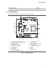
1. Board Components.................................................................................................... 11
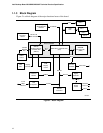
2. Block Diagram ........................................................................................................... 12
3. Intel 810E Chipset Block Diagram ............................................................................. 18
4. Back Panel I/O Connectors ....................................................................................... 39
5. Internal I/O Connectors ............................................................................................. 41
6. External I/O Connectors ............................................................................................ 46
7. Location of the Jumper Block .................................................................................... 49
8. Board Dimensions ..................................................................................................... 51
9. I/O Shield Dimensions ............................................................................................... 52
10. High Temperature Zones........................................................................................... 55
11. Memory Map of the Flash Memory Device ................................................................ 62
Tables
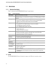
1. Feature Summary...................................................................................................... 10
2. Specifications ............................................................................................................ 13
3. Processors Supported by the Board.......................................................................... 16
4. System Memory Configuration................................................................................... 17
5. Supported Graphics Refresh Rates........................................................................... 22
6. LAN Connector LED States ....................................................................................... 26
7. Effects of Pressing the Power Switch ........................................................................ 27
8. Power States and Targeted System Power ............................................................... 28
9. Wake Up Devices and Events ................................................................................... 29
10. Fan Connector Descriptions ...................................................................................... 30
11. System Memory Map................................................................................................. 33
12. I/O Map ..................................................................................................................... 34
13. DMA Channels .......................................................................................................... 35
14. PCI Configuration Space Map ................................................................................... 36
15. Interrupts ...................................................................................................................36
16. PCI Interrupt Routing Map......................................................................................... 37
17. USB Connectors........................................................................................................ 40
18. VGA Port Connector.................................................................................................. 40
19. LAN Connector.......................................................................................................... 40
20. Audio Line Out Connector ......................................................................................... 40