


Technical Reference
47
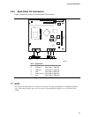
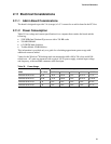
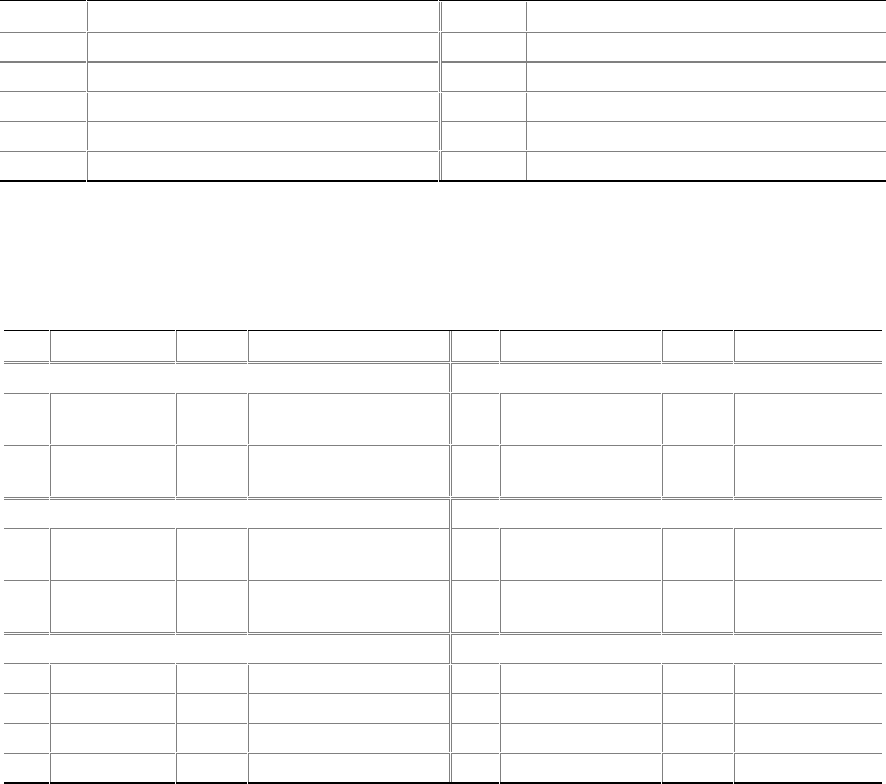
2.8.3.1 USB Port Connector
Table 30 lists the signal names of the USB port connector.
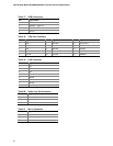
Table 30. USB Port Connector (J7A1)
Pin Signal Name Pin Signal Name
1 USB_PWR 2 USB_PWR
3 USB_P2RL# 4 USB_P3RL#
5 USB_P2RL 6 USB_P3RL
7 Ground 8 Ground
9 Key (no pin) 10 USB_FP_OC
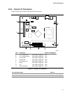
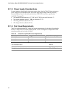
2.8.3.2 Front Panel Connector
Table 31 lists the signal names of the front panel connector.
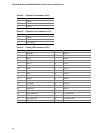
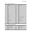
Table 31. Front Panel Connector (J8C1)
Pin Signal In/Out Description Pin Signal In/Out Description
Hard Drive Activity LED Power /Sleep / Message Waiting LED
1 HD_PWR Out Hard disk LED pull-up
(330 Ω) to +5 V
2 HDR_BLNK_GRN Out Front panel
green LED
3 HD_LED# Out Hard disk active LED 4 HDR_BLNK_YEL Out Front panel
yellow LED
Reset Switch Power Switch
5 GND Ground 6 SW_ON# In Front panel
power switch
7 FP_RESET# In Front panel Reset
button
8 GND Ground
Infrared Port Miscellaneous
9 +5 V Out IR Power 10 N/C In Not connected
11 IRRX In IrDA serial input 12 GND Ground
13 GND Ground 14 (Pin removed) Not connected
15 IRTX Out IrDA serial output 16 +5 V Out Power