


Intel Desktop Board D810EMO/MO810E Technical Product Specification
48
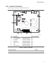
2.8.3.2.1 Power / Sleep / Message Waiting LED Connector
Pins 2 and 4 can be connected to a single- or dual-colored LED. Table 32 lists the possible states
for a single-colored LED. Table 33 shows the possible states for a dual-colored LED.
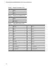
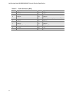
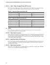
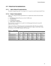
Table 32. States for a Single-colored Power LED
LED State
Description ACPI State
Off Not running S1, S3, S5
Steady Green Running S0
Blinking Green Running/message waiting S0
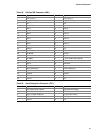
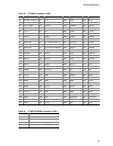
Table 33. States for a Dual-colored Power LED
LED State Description ACPI State
Off Power off S5
Steady Green Running S0
Blinking Green Running/message waiting S0
Steady Yellow Sleeping S1, S3
Blinking Yellow Sleeping/message waiting S1, S3
✏ NOTE
To use the message waiting function, ACPI must be enabled in the operating system and a
message-capturing application must be invoked.
2.8.3.2.2 Power Switch Connector
Pins 6 and 8 can be connected to a front panel power switch. The switch must pull pin 6 to ground
for at least 50 ms to signal the power supply to switch on or off. (The time requirement is due to
internal debounce circuitry on the board.) At least two seconds must pass before the power supply
will recognize another on/off signal.
2.8.3.2.3 Hard Drive Activity LED Connector
Pins 1 and 3 can be connected to an LED to provide a visual indicator that data is being read from
or written to a hard drive. For the LED to function properly, an IDE drive must be connected to
the onboard IDE interface.
2.8.3.2.4 Reset Switch Connector
Pins 5 and 7 can be connected to a momentary SPST type switch that is normally open. When the
switch is closed, the board resets and runs the POST.