148 Technical Product Specification
Order #273817
Intel NetStructure
®
MPCBL0001 High Performance Single Board Computer
Contents
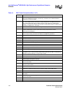
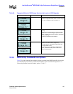
Table 98. J18 Pin Assignments
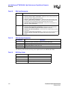
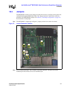
Table 99. J16 Jumper Assignments
Table 100. J37 Jumper Assignments
Lattice* Compatible JTAG Header PS/2 Keyboard/Mouse Header
1 +3.3 VSB 2 MDAT (PS/2 mouse data)
3 TDO 4 MCLK (PS/2 mouse clock)
5 TDI (H0_SKTOCC#) 6 GND
7 ISPEN# 8 +5 V (through polyswitch)
9 Key - no pin or connection 10 KBDAT (PS/2 keyboard data)
11 TMS (H1_SKTOCC#) 12 KBCLK (PS/2 keyboard clock)
13 GND 14 Key—no pin or connection
15 TCK (WDT_EN) 16 GND
NOTE: Processors must be removed before using the Lattice JTAG interface.
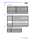
Jumper Function
J16-1 to 3 CLEAR_PASSWD: This jumper is used in the event the system will not boot
because the BIOS password is unknown.
J16-3 to 5 CLEAR_CMOS: This jumper is used in the unlikely event a CMOS data corruption
keeps the system from booting (or getting to SETUP).
J16-4 to 6 RTC_RST: Hardware Reset of RTC. When asserted, this signal resets register bits
in the RTC well and sets the RTC_PWR_STS bit (bit 2 in GEN_PMCON3 register).
J16-2 to 4 FRC_UPD (IPMC F/W): This jumper is used to put the firmware into a forced update
mode. Administrators could use this feature to force the firmware to enter into
update mode and wait for an update through the KCS interface. Useful when some
of the SDR or firmware needs to change. Please note that Sensor scanning/
monitoring is disabled in this mode. Administrators will have to remember to disable
the jumper after an update, or the board will boot again into this update mode.
J16-3 to 4 and
J16-7 to 9 (Default)
Storage posts for jumpers not in use.
J16-8 to 7 Only for debug purposes.
J16-10 to 9 Manufacturing jumper (for testing during board assembly).
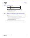
Jumper Function
J37-1 to 2 Use IPMC to control which BIOS ROM to use (default).
J37-3 to 4 Select redundant FWH to be used (FWH1).
J37-5 to 6 Not supported
J37-7 to 8 Not supported


