60 Technical Product Specification
Order #273817
Intel NetStructure
®
MPCBL0001 High Performance Single Board Computer
Contents
1. The reset button is pressed (see Note below). See Figure 14, “MPCBL0001NXX SBC Front
Panel” on page 81 for its location.
2. A processor shutdown special cycle occurred.
3. An INIT command from Port 92h I/O register (refer to the Intel
®
82801CA I/O Controller Hub
3 (ICH3-S) Datasheet for information about this register).
4. An INIT command from Port CF9h I/O register.
5. A keyboard reset command (ICH3 RCIN# signal asserted).
6. The IPMC may also directly assert the INIT signal; WDT #1 expires and is configured for a
soft reset.
7. Processor BIST is enabled and a hard reset is initiated from the Port CF9h register. This asserts
the INIT signal but is not classified as a soft reset since CPU reset is also asserted.
8. OS reboot commands (eg: "shutdown -r now" or "reboot" in Linux).
9. A processor INIT may also be initiated through an APIC “init” message. This message may
target a specific processor or all processors. This “init” is an internally generated event (No
INIT signal is asserted) so the IPMC is unable to detect this occurrence.
Note: The reset button (RESET_PB#) is an input to the IPMC. There are also IPMI commands to reset
the board and change power states through the software. However, the reset button is a last resort
because the user must be physically present at the chassis to reset the board.
After a Soft Reset/CPU Init, the BIOS code executes and determines if the reset is a warm boot or
a cold boot. A warm boot restarts the system and keeps memory above the 8 MByte boundary
intact. During a warm boot the MCH is not reset, allowing DRAM refresh to continue during and
over the soft reset event. A cold boot sets the state of all peripherals to the same state they would be
in if a hard reset were triggered.
3.12.4 Warm Boot
A warm boot occurs when the processor is booting after a soft reset request. To qualify as a warm
boot, the reset counter located at 40h:D0h must be non-zero (by default, the reset counter and reset
flag are initialized to 10 and 1234h by BIOS after a cold boot.) Execution starts at the reset vector.
The BIOS initializes and configures all devices except for memory. Memory contents remain intact
except for the first 8 MBytes. The BIOS uses the first 8 MBytes during POST, but does not modify
the reset flag or the reset counter. MCH is not reset, allowing DRAM refresh to continue during the
warm boot.
Note: On every warm boot, BIOS automatically decrements the reset counter by one. When the reset
counter reaches zero and the soft reset is initiated, a cold boot occurs instead of warm boot.
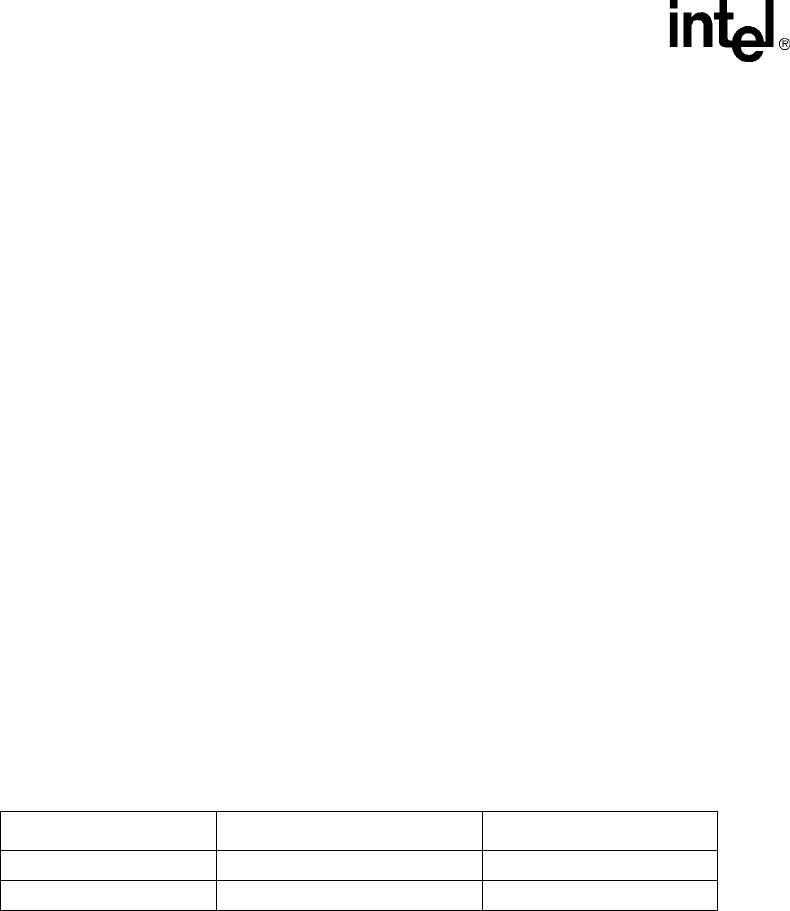
Table 24. Reset Request
Reset Request Signal Activated Type
Hard Reset Full reboot
Soft Init Partial reboot


