


Appendix A: Technical Specifications
45
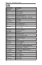
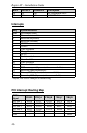
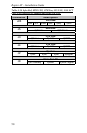
Address (hex) Description
03D4-03D5 Video (VGA)
03DA Video (VGA)
03E8-03EF COM3 (if selected)
03F0-03F5 Floppy Channel 1
03F6 Primary IDE channel command port
03F7 Floppy Channel 1 command
03F7, bit 7 Floppy disk change channel 1
03F7, bits 6:0 Primary IDE channel status report
03F8-03FF COM1 (default)
04D0-04D1 INTC-1 Edge/Level Control
0CF8-0CFB - 4
bytes
PCI configuration address register
0CF9 Reset control register
0CFC-0CFF - 4
bytes
PCI configuration data register
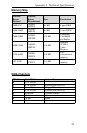
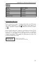
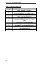
On-board Devices
DISK ON CHIP 1
Memory address selectable between:
D000(default), D400, D800, DC00.
DISK ON CHIP 2
Memory address selectable between:
D000, D400(default), D800, DC00.
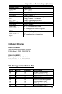
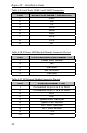
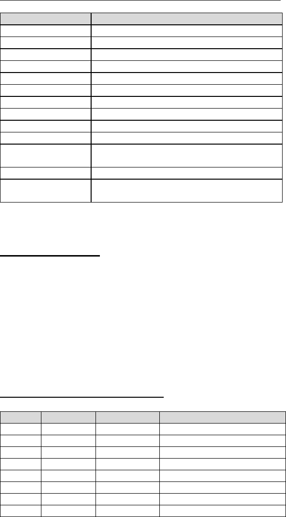
PCI Configuration Space Map
Bus # Device # Function # Description
00 00 00 440BX (Host Bridge)
00 07 00 PIIX4 PCI/ISA bridge
00 07 01 PIIX4 IDE bus master
00 07 02 PIIX4 USB
00 07 03 PIIX4 Power Management
00 0F 00 PCI expansion slot 1
00 10 00 PCI expansion slot 2
00 12 00 PCI expansion slot 3