


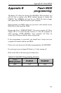
Appendix A: Technical Specifications
47
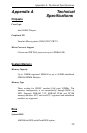
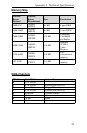
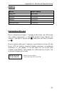
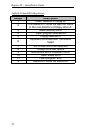
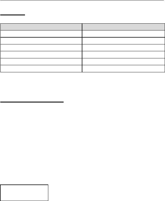
SMBUS
Device Slave Address
MAX1617 0011000b
LM79 0101101b
DIMM0 1010000b
DIMM1 1010001b
DIMM2 1010010b
SDRAM Clock 1101001b
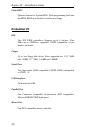
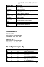
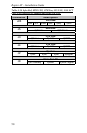
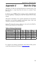
Connectors Pin-out
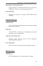
How to identify pin number 1: Looking to the solder side (The board
side without components) of the PCB (Printed Circuit Board), pin
number 1 will have a squared pad J. Other pins will have a circular
pad Q.
How to identify other pins: Connectors type Keyboard, Power AT and
Power ATX are industry standards. Header connectors are numbered
alternately, i.e. pin number 2 is in the other row, but in the same
column of pin number 1. Pin number 3 is in the same row of pin 1, but
in the next column and so forth.
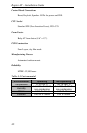
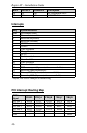
1 3z 5z 7z 9z
2z 4z 6z 8z10z
Header 10 pin connector
View from solder side of the PCB