


10
CONTROLS, INDICATORS AND CONNECTORS
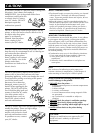
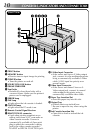
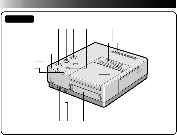
Front View
1
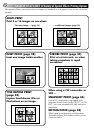
PRINT button
2 MEMORY button
• Press to store an input image for printing.
3 POWER button
• Turns the printer on and off.
4 SOURCE/ON LINE button
5 FRAME STABILIZER
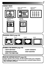
6 Vent holes
• Periodically clean these holes with a
vacuum cleaner. Make sure the printer’s
power cord is unplugged.
7 ERROR lamp
8 INK lamp
• Lights when the ink cassette is loaded.
9 ON LINE lamp
• Lights when the PC mode is on.
0 Remote Control Signal Receiver
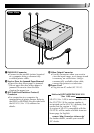
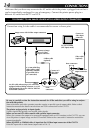
! REMOTE PAUSE connector
• Used when printing snapshots or an
editing index from a JVC camcorder or
video cassette recorder. Connect a
commercially available ø3.5mm mini
plug to either the camcorder’s editing
jack or the video cassette recorder’s
R.A.EDIT or SPECIAL FUNCTION jack.
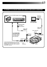
@ S-Video Input Connector
• If the source unit has an S-Video output
jack, connect it to the multimedia printer
using a commercially available S-Video
cable. S-VHS input has priority over
normal inputs.
# Video Input Connector
• If the source unit doesn’t have an S-
Video output jack, connect its normal
video output to the printer using a
commercially available video cable.
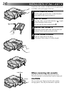
$ Paper Tray Insertion Slot
• Insert the paper tray into this slot.
% Output Tray
• Printed sheets are stacked here.
* Be sure to open the tray when using the
printer.
^ Ink Cassette Insertion Slot
• Open this to load or unload the ink
cassette.
1 2
345
7
8
9
0
6
!@ #
$
%
^