


30
Network pack setup
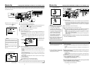
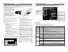
Controlling GY-DV5000/KA-DV5000 via LAN card
With the Network Pack, GY-DV5000/KA-DV5000 can be controlled via LAN.
It is also possible to playback video and audio from KA-DV5000 on your PC in the STREAMCAPTURE screen in realtime (live display)
as well as save data to files. However, note that video and audio from KA-DV5000 can be played back only on one PC at a time.
Peer-to-peer connection that directly connects the unit with a PC is explained here.
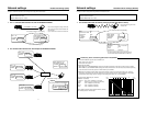
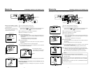
● There are the 3 types of users for Web access:
● Users referred as “jvc” (can be changed) that can
perform all operations, “ENCODE” users that can
view all data but only change the encoding
settings, and “BROWSE” users that can only view
data.
● The default password for each user type is “ka-
dv5k” for “jvc” users, first 4 characters of the
password set for “jvc” users for “ENCODE” users
(default is “ka-d”) and fixed password of “ka-dv”
for “BROWSER” users.
● The following is an explanation when login is made
a user permitted with all operations. In the case of
other users, the OK button and Cancel button will
be disabled even if operations on the screen are
allowed.
MONITOR
EDITSEARCH
FILTER
STATUS
SHUTTER
MENU
AUTO IRIS
BACK L
NORMAL
SPOT L
STRETCH
NORMAL
COMPRESS
FULL AUTO BLACK LOLUX
MODE
POWER
ON OFF
VTR
OPEN
VTR
CAM
1
3200K
5600K
5600K
5600K
ND
/
/
ND
2
.3
.4
1
8
1
64
CH-1
AUDIO INPUT
AUDIO SELECT
CH-2
CH-1CH-2
FRONT
REAR
AUTO
MANUAL
AUDIO
LEVEL
CH-1 CH-2
PULL
OPEN
LCD BRIGHT DISPLAY
NETWORK
PACK
KA-DV5000
POWER
SUPPLY
ON OFF
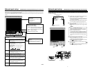
GY-DV5000
KA-DV5000
Socket Com: EA2900-117 (USA)
EA2903-162 (Europe)
EA2906-194 (Asia)
(CF memory card adapter (PCMCIA TYPE I/II
specifications)(sold separately) is required for
inserting this card.)
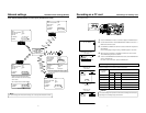
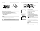
1.
Turn your PC and GY-DV5000 and KA-DV5000 power off.
2.
Insert the PCMCIA LAN card to specify into KA-DV5000.
3.
Connect the unit and PC using a 10/100 BASE-T cross cable.
4.
Turn the PC and GY-DV5000 and KA-DV5000 power on.
5.
Insert a recordable DV cassette tape.
6.
PC settings
● Set the LAN card driver according to the manual provided
by the card manufacturer.
● Network settings (
☞
page 13)
q Set the following items in the TCP IP properties:
* DHCP server is not used.
IP address: 192.168.100.101
Subnet mask: 255.255.255.000
w Setting the proxy server.
• Set the proxy server using the “LAN SETTINGS” of
Windows.
• When using peer-to-peer communication that directly
connects the PC and KA-DV5000, deselect the “Use a
proxy server” checkbox.
• When the “Use a proxy server” setting must be en-
abled due to a LAN environment (in-company LAN,
etc.), click “Advanced...” and input the IP address of
GY-DV5000 in “Exceptions” of the “Use a proxy server”
setting.
(
☞
“About proxy servers,” Page 45)
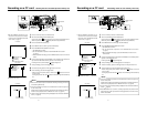
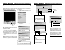
7.
Launch the browser on your PC and enter 192.168.100.101
(default factory setting) in the address bar and press ENTER.
● A confirmation window for user ID and password appears.
8.
Input the user ID and password.
q For the user ID, input “jvc” (factory setting).
For the password, input “ka-dv5k” (factory setting) or the
name set in the NETWORK SET [2/2] menu screen.
(
☞
page 10)
w Check to make sure the inputted user ID and password
are correct and click the OK icon.
(Check “Save password” so that the password does not
need to be inputted for future accesses.)
9.
If the user ID and password are correct, the NETWORK PACK
SETUP screen appears on the PC monitor.
● GY-DV5000/KA-DV5000 settings and operations can be
controlled using the NETWORK PACK SETUP. (
☞
page
31)
PC
?X
OK
Cancel
Enter Network Password
Please enter tour authentication information.
Resource
secured
User name:
Password:
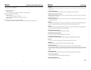
Caution
●When setting the NETWORK PACK SETUP screen (CAM &
VTR CONTROL, NETWORK SETUP, PORT SETUP or EN-
CODE PARAMETERS) and the same menu screen is dis-
played on the LCD screen or viewfinder of GY-DV5000, val-
ues set in the NETWORK PACK SETUP screen will not ap-
pear on menu screen of the LCD screen or the viewfinder of
GY-DV5000.
The values set in the NETWORK PACK SETUP screen will
appear after the menu screen of GY-DV5000 is closed once
and reopened.
●During camera/VTR control, noise may be heard from the
speakers. However, this is not a malfunction. If the noise be-
comes irritating, open the “Sound & Multimedia” property from
the Windows Control Panel and set the sound of “Windows
Explorer Start Navigation” of “Sound Events” to off.
* For setting details, see Windows’ Help.
●Check to make sure that NET REMOTE in the OTHERS [1/2]
menu screen of GY-DV5000 is set to “ON”. Camera control
will not be available when NET REMOTE is set to “OFF”.
●Depending on the cache setting of your browser, the param-
eters updated in the Camera menu may not be effective im-
mediately.
Set the LAN card
driver by following
the instructions on
manual provided
by the card
manufacturer.
10/100 BASE-T
cross cable
31
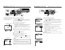
Network pack setup
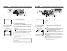
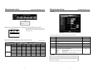
CAM & VTR CONTROL screen
When the correct user ID and password are accepted, the following Streamcorder screen appears.
In the CAM & VTR CONTROL screen, camera adjustments of GY-DV5000 and VTR controls can be made.
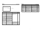
\Camera Control
Setting range
● When setting AUTO to ON, items other than LOLUX will not be available.
● When setting BARS to ON, items other than AUTO and LOLUX will not be available.
● When setting GAIN to ALC, IRIS and SHUTTER will not be available.
Screen selection
Clicking will display the se-
lected screen.
Clicking the OK icon will
confirm the inputted set-
ting.
Setting
Select the setting from the
pull-down menu.
Adjustment mode selection
Check the desired adjust-
ment mode.
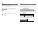
Item
AUTO
BARS
WHITE BAL
IRIS
Lolux
GAIN
SHUTTER
Adjustment mode
AUTO
MANUAL
ON
OFF
ALC
STEP
0dB
STEP
OFF
V-SCAN
Setting/description
ON: Auto mode on. Items other than LOLUX cannot be set.
OFF: Auto mode off
ON: Color bar signals are outputted. Items other than AUTO and LOLUX cannot be set.
OFF: Color bar signals are not outputted.
FAW: Full white balance mode
PRESET: White balance will be in the preset state. (3200K)
MEMORY A, B: White balance setting stored in the GY-DV5000 memory will be used.
Auto iris mode. Iris will be adjusted within the following range:
[–3, –2, –1, 0, +1, +2, +3]
Manual iris mode. Iris will be adjusted within the following range:
[CLOSE, F16, F11, F8, F5.6, F4, F2.8, F2, OPEN]
Lolux mode
ALC (Auto Level Control) mode. IRIS and SHUTTER cannot be set
Gain can be set within the following range. 0dB is not available.
[–3dB ~ 18dB]
0dB (Sensitivity is not increased)
Shutter speed can be set within the following range:
U model: [1/7.5, 1/15, 1/30, 1/100, 1/250, 1/500, 1/1000, 1/2000, 1/4000, 1/10000]
E model: [1/6.25, 1/12.5, 1/25, 1/120, 1/250, 1/500, 1/1000, 1/2000, 1/4000/, 1/10000]
Shutter speed will be 1/60 (1/50). ( ): for E model
Although this setting can be canceled, future settings of this item will not be allowed.