


E-8
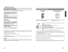
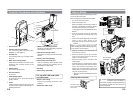
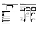
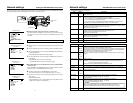
1 Power switch
2 Camera connection terminal
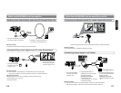
For connecting DV camcorder (GY-
DV5000). (☞ See page 9)
3 PC card slot
For inserting LAN card, Compact Flash
card, etc.
4 Main unit mounting hooks
Used when mounting to the main unit by
hooking to the cut-away section of the
camcorder.
5 EJECT button
Press when ejecting card.
6 Service terminal
Do not use.
7 Lock/release button
To open the cover, press the [PUSH]
section and lift.
8 Cover
Cover for the PC card slot. The cover can
be removed by opening and twisting in a
backward direction.
9 Battery case mounting screws
Screws for mounting the battery case after
attaching the main unit.
0 Main unit mounting screws
Used when mounting the main unit to the
camera.
A Battery case wire passage
B Cable clamp mounting hole
Hole for attaching the included cable
clamp. Remove the bushing before
attaching the cable clamp.
C Bushing
D Cable clamp (included)
For use with LAN card cable
and LAN cable.
¡ Remove the busing.
Remove by pinching the head of the
bushing.
™ Attach the cable clamp
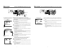
Controls, Connectors and Indicators
K
A
-D
KA-DV
5
00
0
V5000
NETWNETWORK PORK PACKCK
POWER
SUPPLY
NETWORK
PAC K
KA-DV5000
ON
OFF
2
0
1
4
8
3
5
B
C
9
6
A
7
¡
™
D
E-9
English
7
6
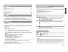
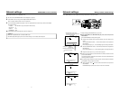
How to Attach
MONITOR
EDITSEARCH
FILTER
STATUS
SHUTTER
MENU
AUTO IRIS
BACK L
NORMAL
SPOT L
STRETCH
NORMAL
COMPRESS
FULL AUTO BLACK LOLUX
MODE
POWER
ON OFF
VTR
OPEN
VTR
CAM
1
3200K
5600K
5600K
5600K
ND
/
/
ND
2
.3
.4
1
8
1
64
CH-1
AUDIO INPUT
AUDIO SELECT
CH-2
CH-1 CH-2
FRONT
REAR
AUTO
MANUAL
AUDIO
LEVEL
CH-1 CH-2
PULL
OPEN
LCDBRIGHT DISPLAY
POWER
ON OFF
VTR
1
2
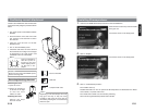
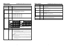
Below is the procedure for attaching the main
unit to the DV camcorder.
Mount using the procedure shown below.
1
Turn off the camcorder power.
2 Remove the battery case.
Remove the battery case mounting screws on
the back of GY-DV5000, remove the battery
case and remove the internal connector.
☞ See page 35 of the GY-DV5000 Instruction
Manual
3 Insert the connector wire of the camcorder
through the back of the network pack to the
front.
4 Tilt the network pack diagonally, set the upper
hooks on the cut-away section of the
camcorder from the top and turn downward.
5 Align the connectors of the network pack and
camcorder and connect.
6 Mount the network pack to the camcorder
using the 2 mounting screws on the lower
section of the network pack.
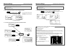
7 Mount the battery case on the back of the
network pack.
Insert the cushion on the back of the network
pack, connect the connector from the network
pack to the connector on the battery case,
clamp wires as shown below, and fix the
battery case to the back of the network pack
using the mounting screws.
☞ See page 35 of the GY-DV5000 Instruction
Manual
Make sure the cushion does not shift
when hooking the network pack to the cut-
away section of the camera.
Caution
BH cushion
(included)
3
5
4
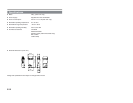
Fix unused connector wire to the back of
the camera or back of network pack using
the clamps so that the wire does not
become pinched.
Caution
Storing the connector
To battery case
Clamps
Place vertically
and clamps