


18
Preparation (continued)
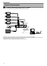
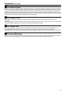
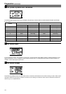
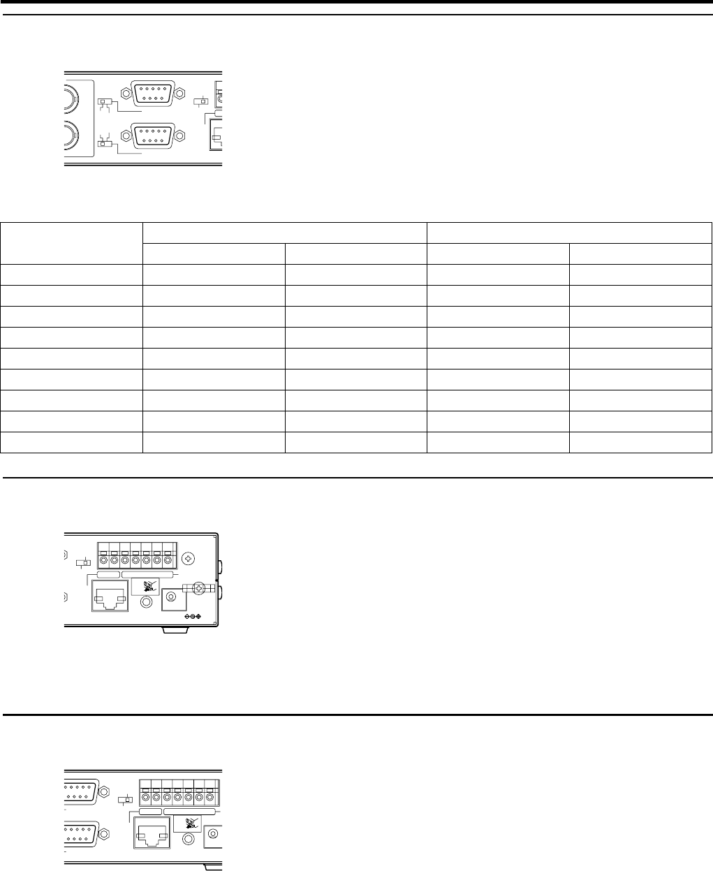
Ⅵ4-3 [COM1,2] Serial Port Terminals
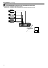
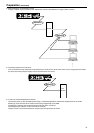
Connect the device (camera, etc.) to be controlled to the serial port. Use the switch to switch between RS-232C and RS-485.
● Pin Layout
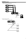
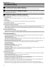
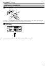
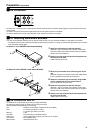
Ⅵ4-4 Alarm Input
For connecting the sensor. This consists of 4 input and 1 ground terminals. Either Make or Break is selected depending on the
setting, and sensors of the no-voltage A contact output (normally open), no-voltage B contact output (normally closed) or no-
voltage C contact output type may be used.
Ⅵ4-5 Alarm Output
The [OUT] and [COM] terminals form the make contact. Connect the device that is to be turned on during an alarm. Alarm output
changes to break when the power of VN-E4 is turned off. Upon starting up VN-E4, the alarm output is restored to the previous
state.(A pg. 54, A8. SpecificationsB)
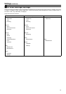
Pin No.
When RS-232C is selected When RS-485 is selected
Name Function Name Function
1 (NC) (Not in use) RX+ + Receiving End
2 RXD Receive data RX -- Receiving End
3 TXD Send data TX -- Sending End
4 (NC) (Not in use) TX+ + Sending End
5 GND Grounding GND Grounding
6 (NC) (Not in use) (NC) (Not in use)
7 (NC) (Not in use) (NC) (Not in use)
8 (NC) (Not in use) (NC) (Not in use)
9 (NC) (Not in use) (NC) (Not in use)
SERVICE
CONTROL
RS-485
RS-232C
OUTPUT
COM2
10BAS
E
2CH
4CH
CO
M
COM1
PUSH
ALARM
SERVICE
CONTROL
INPUT
OUTPUT
10BASE-T/100BASE-TX
COMOUT
1234G
DC5V
RESET
PUSH
A
SERVICE
CONTROL
I
OUTPUT
COM2
10BASE-T/100BASE-TX
COMOUT
1234G
DC5V
RESET
COM1