


9
Introduction (continued)
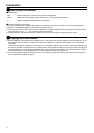
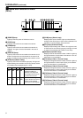
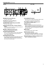
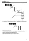
[BACK] [BOTTOM]
M[AUDIO IN] terminal (RCA pin)
For input of audio signals.
N[AUDIO OUT] terminal (RCA pin)
For output of audio signals.
O[VIDEO INPUT 1CH to 4CH] terminal (BNC)
For input of video signals.
P[RS-232C/RS-485] COM1, 2 Protocol Selection
Switch
For switching between RS-232C and RS-485 of COM1 and
COM2. Factory setting is RS-232C.
Q[COM1, COM2] terminal (D-sub 9P)
Serial port for controlling external devices.
R[CONTROL/SERVICE] switch
Switch for switching COM1 to servicing. Select CONTROL
for normal use. Select SERVICE during maintenance.
Factory setting is CONTROL.
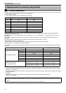
S[ALARM OUTPUT] terminal
The COM and OUT terminals form the make contact. Alarm
output changes to break upon turning off the power of
VN-E4, and alarm output is restored to the previous state
upon turning on the power again.
T[ALARM INPUT] terminal
Input terminal for no-voltage make contact or break contact.
This consists of 4 input and 1 ground terminals.
U[10 BASE-T/100 BASE-TX] LAN terminal
For connecting the network cable.
V[RESET] button
Button for resetting VN-E4. Power will be reset upon
pressing this button and releasing it within 5 seconds. If this
button is pressed for 5 seconds or longer, LEDs from STS
to CH4 will start to blink and all settings will be restored to
their factory defaults.
WWire Clamp
For securing the cable of the AC adaptor.
X[DC 5V] Power Terminal
For connecting the AC adaptor supplied.
VN-E4 does not come with a power switch. It will start up
automatically upon supply of power using the AC adaptor.
YThe MAC address of VN-E4 is displayed on the
label in hexadecimal numbers.
PUSH
ALARM
AUDIO
VIDEOINPUT
IN
OUT
SERVICE
CONTROL
RS-485
RS-232C
INPUT
OUTPUT
COM2
10BASE-T/100BASE-TX
2CH
4CH
3CH
1CH
COMOUT
1234G
DC5V
RESET
COM1
M
R
S
TW
U
V
X
N
O
PQ
Y