


KRAMER: SIMPLE CREATIVE TECHNOLOGY
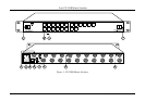
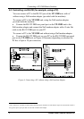
Your RC-1616 Remote Control
12
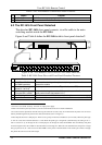
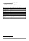
Table 7: RC-1616 Remote Control Rear Panel Features
# Feature Function
1 9V DC 1A Connector +9V DC connector for powering the unit
1
2 10 Base T Port Connects to the 10 Base T network (used for remote panels)
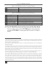
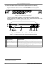
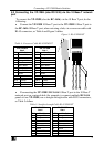
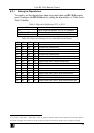
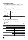
6.2 The RC-1616 Front Panel Detached
The detached RC-1616 front panel connects via a flat cable to the main
switching module inside the RC-1616.
Figure 8 and Table 8 define the RC-1616 with its front panel detached
2
:
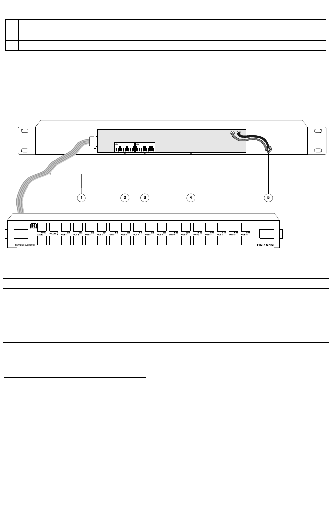
Figure 8: RC-1616 Remote Control with its Front Panel Detached
Table 8: RC-1616 Front View with Front Panel Detached Features
# Feature Function
1 9-wire Ribbon Flat Cable
with DB9M connectors
Connects the circuitry on the (detached) front panel to the main
electronics module
2 Dipswitches (first set 1 to 8 is
named: S1-1 to S1-8)
3
Set the panel’s network address
4
(by default, set to OFF)
3 Dipswitches (second set 1 to
8 is named: S2-1 to S2-8)
3
Determine the single bus or the “XY” operation, as well as the video and
audio control levels (see section 6.2.1)
4 Main Switching Module Provides easy accessibility for service and repair
5 Power Wires The red wire connects to the “+9V” and the black wire connects to the “GND”
1 Connect to an external ‘desk-top’ universal AC input power supply
2 Slide-in units held in place by latches to prevent accidental disconnection in mobile installations
3 You can access the dipswitches without removing the unit from its rack, as they are located inside the panel. You can access
them by unfastening the front panel via the slide action latches (item 1 in Figure 7)
4 These dipswitches have a dual purpose. There are two groups of 256 network addresses (512 in total). When the panel type
is ‘XY’ S1 to S8, select network addresses 1 to 256. When the panel type is ‘Single bus’ (determined by the setting of S2-1 –
refer to section 6.2.1), S1 through S5 serve a dual purpose. S1 through S5 select the OUTPUT bus controlled by that panel
and S1 through S5 select the 5 LSBs of network address 257 through 512. When the scan determines that the panel is a single
bus type panel, S1-6, S1-7 and S1-8 are the three MSB’s of the panel’s network address. This scheme puts a limit of 8 single
bus panels that can be set to the same output