


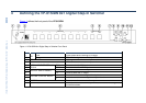

VP-81SIDN - Connecting the VP-81SIDN 8x1 Digital Step-In Switcher
11
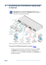
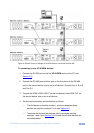
2. Connect a DVI video source (for example, a computer graphics source) to
the LOCAL INPUTS DVI connector, and the computer’s unbalanced stereo
audio source to the LOCAL AUDIO INPUT DVI connector.
3. Connect an HDMI video source to the LOCAL INPUTS HDMI connector.
4. Connect the TP OUT RJ-45 connector to a compatible TP receiver up to
50m (164ft), for example, PT-572+.
5. Connect the S/PDIF RCA digital audio output to an audio acceptor (for
example, a DAT recorder).
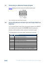
6. Connect the balanced audio 5-pin terminal block (see Section 6.1) to an
audio acceptor (for example, a balanced stereo audio amplifier).
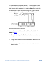
7. Connect up to ten remote, contact closure input selection switches to the
REMOTE terminal block (see Section 6.2).
8. Connect the Ethernet RJ-45 TP port directly or via a LAN to a PC controller.
Alternatively, you can connect a PC and/or controller to the:
RS-232 port (see Section 6.3)
RS-485 port (see Section 6.4)
9. Connect the power cord.
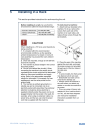
Note: When signal sources are disconnected from inputs, signal acceptors (for
example, a projector) may not go into standby mode automatically. We therefore
recommend that you turn off the VP-81SIDN and/or the acceptor.
Note: When using the PT-572+ in conjunction with the VP-81SIDN do not connect
the 12V power supply to the PT-572+.