


VP-81SIDN - Connecting the VP-81SIDN 8x1 Digital Step-In Switcher
13
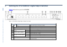
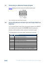
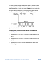
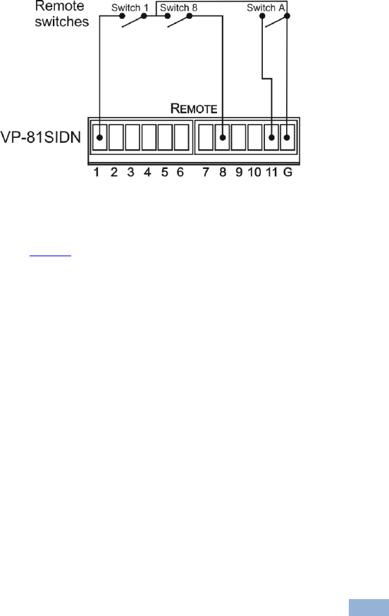
The following example illustrates three switches (1, 8 and A) connected so as to
remotely control inputs 1 and 8, and select an output respectively. Connected as
shown, pressing switch 1 causes input 1 on the VP-81SIDN to be the active input,
and pressing switch 8 causes input 8 to be the active input. Pressing switch A
causes the output selection to toggle between the TP and HDMI outputs.
Figure 5: Remote Input Selection Switch Wiring
To connect remote input/output selection switches as illustrated in the
example in Figure 5:
1. Connect Switch 1 to pins 1 and G on the terminal block (remote step-in for
input 1).
2. Connect Switch 8 to pins 8 and G on the terminal block (remote step-in for
input 8).
3. Connect Switch A to pins 11 and G on the terminal block (remote output
selection toggle).