


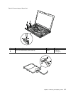
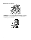
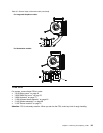
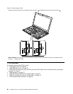
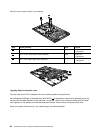
Table 31. Removal steps of CPU
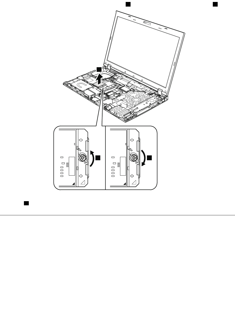
Rotate the head of the screw in the direction shown by arrow 1 to release the lock; then remove the CPU 2 .
2
1 a
When installing: Place the CPU on the CPU socket, and then rotate the head of the screw in the direction shown
by arrow a to secure the CPU.
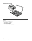
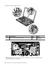
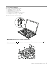
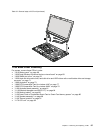
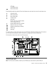
1170 LCD unit
For access, remove these FRUs in order:
• “1010 Battery pack” on page 68
• “1030 DIMM slot cover” on page 70
• “1050 Hard disk drive slot cover, hard disk drive and HDD rubber rails or solid state drive and storage
converter” on page 71
• “1060 Keyboard” on page 73
• “1080 PCI Express Mini Card for wireless LAN” on page 77
• “1090 PCI Express Mini Card for wireless WAN” on page 79
• “1100 Keyboard bezel assembly” on page 81
94 ThinkPad T510, T510i, and W510 Hardware Maintenance Manual