


Chapter 2. SPECIFICATIONS
2 - 13
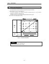
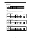
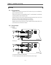
2.5.1 Sampling processing A/D conversion system
The analog values input to the channels designated for sampling processing by the CPU are
converted to digital output values one by one and the digital output values are stored in the
buffer memory.
As the A/D module scans each channel, the value appearing at the instant is written to the
buffer memory as a digital value. The timing of this sampling depends on the number of
channels used, and may be found from the following expression.
Process time = Number of channels used
×
Maximum conversion time (5 ms)
The process time when 4 channels is used, for example, will be 20 msec = 4 × 5 ms
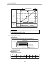
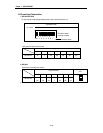
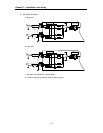
2.5.2 Averaging processing A/D conversion system
The A/D module makes the A/D conversion for any channels to which averaging processing
has been specified from the CPU. Using a pres et count, an average is calculated (excluding the
maximum value and the minimum value) and stored to the buffer memory. The preset count
can be set as 2 to 255 times.
The time in which the average value by this processing is stored in the buffer memory varies
with the number of channels used.
Processing time = Count setting
×
No. of channels
×
5ms (Max conversion time)
The processing time when count value is 50 and 4 channels are used, for example, will be 50 ×
4 × 5ms = 1000ms.
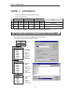
2.5 Processing specifications