


Chapter 8 MK Programming
8 - 3
8.2 Example programming
8.2.1 A program for comparison of A/D converted value
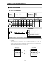
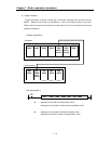
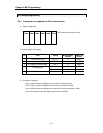
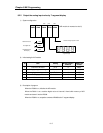
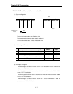
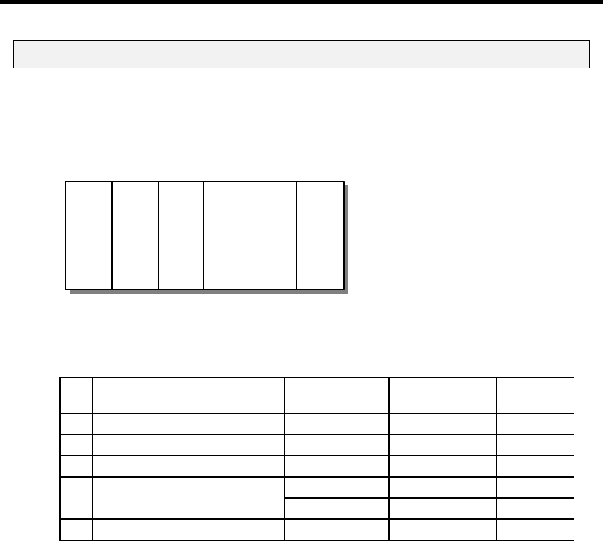
1) System configuration
(A/D module is mounted on slot 0)
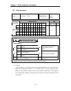
2) Initial setting for A/D module
No Item Setting
Buffer memory
address
Data to be
written
1 Channel to be used Ch 0, 2, 4 0 h0015
2 Analog input type and range DC4~20mA 1 h0000
3 Averaging processing enable Ch 2, 4 2 h0014
Ch2 : 100 times 5 h0064
4 Averaging count
Ch 4 : 50 times 7 h0032
5 Validate setting 11 h0001
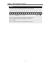
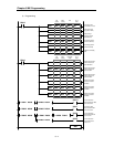
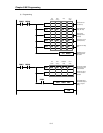
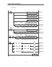
3) Description of program
Turns on P0010 bit when the digital value of channel 0 is less than 2000
Turns on P0011 bit when the digital value of channel 2 is greater than 3600
Turns on P0012 bit when the digital value of channel 4 is in the range of 2000 ~ 3600
Turns on the P0013 bit when the digital value of channel 4 is 2800.
GM3-
PA2A
K7P-
30AS
G3F-
AD3A
G3I-
D22A
G3Q-
RY4A
G3Q-
RY4A