Chapter 8 MK Programming
8 - 1
8 MK Programming
8.1 Basic programming
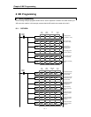
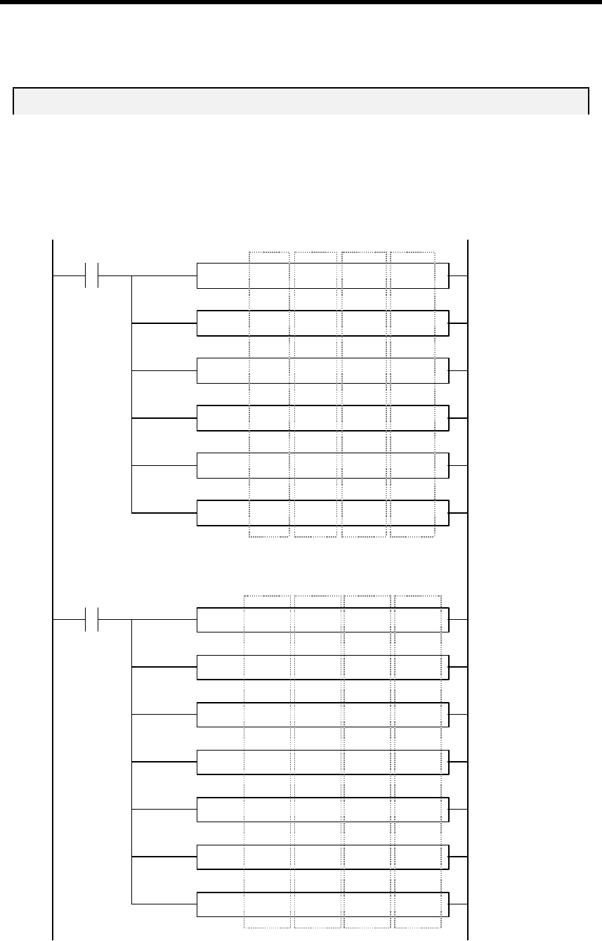
The following example program shows how to set the operation condition for buffer memory of
A/D conversion module. In this example, assume that the A/D module is mounted on the slot 2.
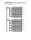
8.1.1 G6F-AD2A
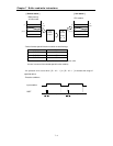
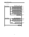
PUT 0002 00000 h000B 00001
PUT 0002 00001 00000 00001
PUT 0002 00002 h0009 00001
PUT 0002 00003 00100 00001
PUT 0002 00006 00050 00001
PUT 0002 00007 00001 00001
GET 0002 00008 D0108 00001
GET 0002 00009 D0109 00001
GET 0002 00011 D0111 00001
GET 0002 00012 D0112 00001
GET 0002 00013 D0113 00001
GET 0002 00014 D0114 00001
GET 0002 00016 D0116 00001
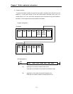
Slot
number
Buffer
memory
Data
No. of
words
Channel to be used
(use channel 0, 1, and 3)
Assign analog input
range (DC4 ~ 20mA)
Assign average
processing channel
(channel 0 and 3)
Set Averaging count of
channel 0 (100 times)
Set Averaging count of
channel 3 (50 times)
Validate the new setting
value
Execution
condition
Execution
condition
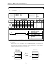
Slot
number
Buffer
memory
Destination
of data
No. of
words
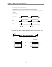
Read the A/D converted
value of channel 0, and
store it into D0108
Read the A/D converted
value of channel 1, and
store it into D0109
Read the A/D converted
value of channel 3, and
store it into D0111
Read the operating
status, and store it into
D0112
Read the error code of
channel 0, and store it
into D0113
Read the error code of
channel 3, and store it
into D0114
Read the error code of
channel 4, and store it
into D0116


