


Chapter 6 Buffer memory
6 - 3
6.2 The Contents and description of buffer memory
6.2.1 G6F-AD2A
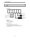
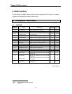
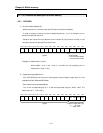
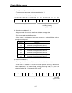
1) Channel enable (Address 00)
- When the power is on, all bits are set as 0 (off) and all channels are disabled.
- In order to enable a channel, set the corresponding bit as 1 (on). For example, turn on
the bit 2 to enable the channel 2.
- Because the conversion time depends on the number of used channel, turning on just
necessary channel can reduce A/D conversion time.
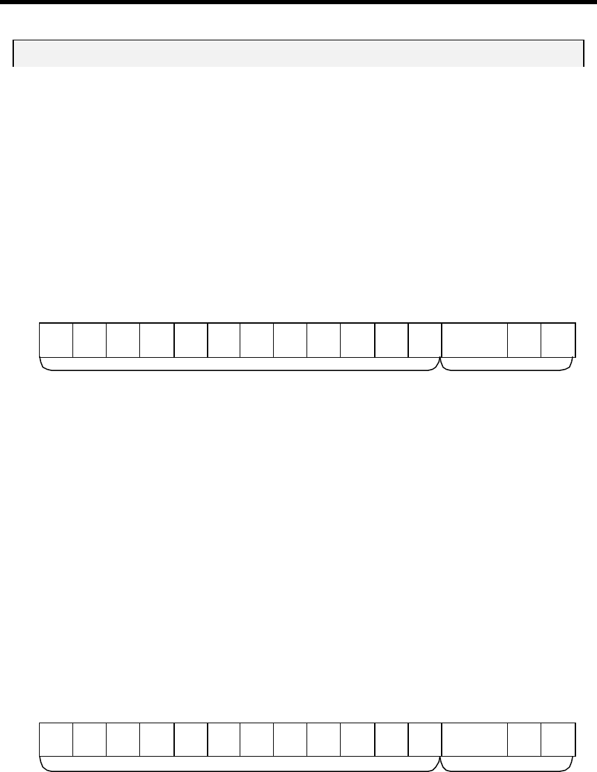
bit15 bit14 bit13 bit12 bit11 bit10 bit9 bit8 bit7 bit6 bit5 bit4 bit3 bit2 bit1 bit0
– – – – – – – – – – – – Ch3 Ch2 Ch1 Ch0
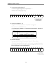
Example) To enable channel 1 and 2 :
Write h0006 ( turn on bit 1 and 2 ) to buffer 00, and sampling time is
obtained as 2 × 5ms = 10ms.
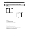
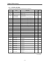
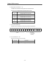
2) Output data range (Address 01)
- Only G6F-AD2A has the function of selecting the range of digital output data. (It is not
available with G3F-AD3A and G4F-AD3A).
- Each channel can be set independently.
- Turn on the corresponding bit as ‘1’ to set the output data range as -2048 ~ 2047. The
default value is ‘0’ ( -48 ~ 4047 ).
bit15 bit14 bit13 bit12 bit11 bit10 bit9 bit8 bit7 bit6 bit5 bit4 bit3 bit2 bit1 bit0
– – – – – – – – – – – – Ch3 Ch2 Ch1 Ch0
Channel enable
0 : A/D conversion disable
1 : A/D conversion enable
Ignored
Assign the output data range
0 : -48 ~ 4047
1 : -2048 ~ 2047
Ignored