


Chapter 8 MK Programming
8 - 4
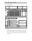
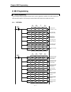
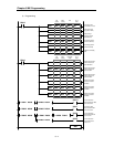
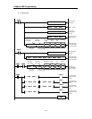
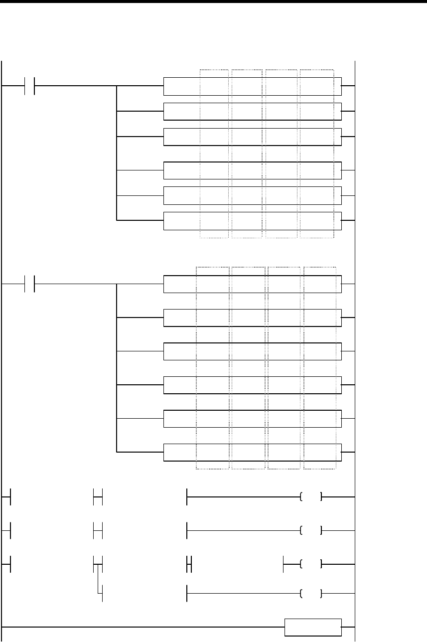
4) Programming
PUT 0000 00000 h0015 00001
PUT 0000 00001 00000 00001
PUT 0000 00002 h0014 00001
PUT 0000 00005 00100 00001
PUT 0000 00007 00050 00001
PUT 0000 00011 00001 00001
GET 0000 00012 D0012 00001
GET 0000 00014 D0014 00001
GET 0000 00016 D0016 00001
GET 0000 00021 D0021 00001
GET 0000 00023 D0023 00001
GET 0000 00025 D0025 00001
Slot
number
Buffer
memory
Data
No. of
words
Channel to be used
(use channel 0, 2, and 4)
Assign analog input
range (DC4 ~ 20mA)
Assign average
processing channel
(channel 2 and 4)
Set Averaging count of
channel 2 (100 times)
Set Averaging count of
channel 4 (50 times)
Validate the new setting
value
Slot
number
Buffer
memory
Destination
of data
No. of
words
Read the A/D converted
value of channel 0, and
store it into D0012
Read the A/D converted
value of channel 2, and
store it into D0014
Read the A/D converted
value of channel 4, and
store it into D0016
Read the error code of
channel 0, and store it
into D0021
Read the error code of
channel 2, and store it
into D0023
Read the error code of
channel 4, and store it
into D0025
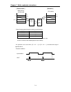
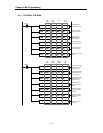
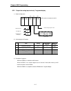
F0010
F0012
= D0021 00000
> 02000 D0012
= D0023 00000
< 03600 D0014
P0011
= D0025 00000
<= 02000 D0016
P0012
= 02800 D0016
P0010
P0013
>= 03600 D0016
END
Turn on P0010 when
D0012 is greater than 2000
and no error at Ch 0
Turn on P0011 when
D0014 is less than 3600
and no error at Ch 2
Turn on P0012 when
D0016 is 2000~3600 and
no error at Ch 4
Turn on P0013 when
D0016 is 2800 and no
error at Ch 4