


Chapter 4. FUNCTION BLOCK
4 - 5
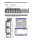
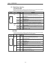
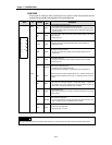
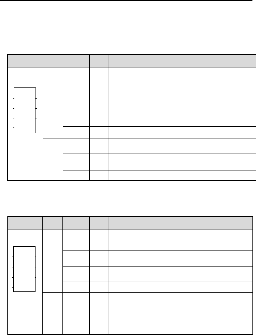
4.2.3 Module Reading - Single Type
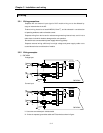
1) G3F-AD3A, G4F-AD3A
Single type of function block for reading the module is performed for only one channel and the specified
channel is used to read output variable of data displayed from A/D conversion digital value.
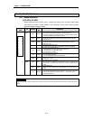
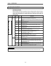
Function
block
I/O Variable
Data
type
Descriptions
REQ BOOL
Function Block Execution Request Area
- The execution of function block reading is requested in this area.
- If the status to be connected with this area is satisfied on the program operation and
input condition changes from low(0) to high(1), function block initialization for the
module is executed.
BASE USINT
Base Module Location Number Area
- The base No. on which A/D conversion module is mounted is written on this area.
- Setting range : 0 ~ 3
SLOT USINT
Slot Location Number Area
- The slot No. on which A/D conversion module is mounted is written on this area.
- Setting range: 0 to 7
Input
CH USINT
Available Channel Specification Area
- Enabled channels are specified to 1 and disabled channels are specified to 0.
DONE BOOL
Function Block Execution Complete Area
- When function block reading is executed with no error, 1 is written and until next
execution, 1 is continuing. When error occurs, 0 is written and operation come to stop.
STAT USINT
Error Code Display Area
- When error occurred during function block initialization, the error code number is
written.
output
DATA INT
A/D Conversion Value Output Area
Output data range : -47 ~ 4048
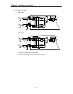
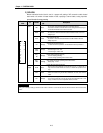
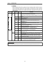
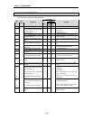
2) G6F-AD2A
Single type of function block for reading the module is performed for only one channel and the specified
channel is used to read output variable of data displayed from A/D conversion digital value.
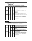
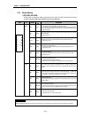
Function
block
I/O Variable
Data
type
Descriptions
REQ BOOL
Function Block Execution Request Area
- The execution of function block reading is requested in this area.
- If input condition is changed from low(0) to high(1), function block initialization for
the module is executed.
BASE USINT
Base Module Location Number Area
- The base No. on which A/D conversion module is mounted is written on this area.
- Setting range : 0
SLOT USINT
Slot Location Number Area
- The slot No. on which A/D conversion module is mounted is written on this area.
- Setting range: 0 to 7
Input
CH BOOL[4]
Available Channel Specification Area
Setting range : 0 ~ 3
DONE BOOL
Function Block Execution Complete Area
- When function block reading is executed with no error, 1 is written and 1 is kept
until next execution. When error occurs, 0 is written and operation come to stop
STAT USINT
Error Code Display Area
- When error occurs during function block reading, the error code number is written.
- Error code is referred to Manual 4.3.
Output
DATA INT[4]
A/D Conversion Value Output Area
- Output data range : -48 ~ 4047 or –2048 ~ 2047
REQ
BASE
SLOT
CH
AD3RD
STAT
DATA
DONE
REQ
BASE
SLOT
CH
DATA
AD2RD
STAT
DONE