


Chapter 5. GM PROGRAMMING
5 -5
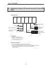
5.2 Programming for Display of
A/D Conversion Value and Error Code on BCD
Display
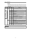
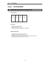
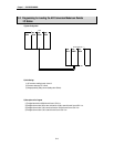
1) System Configuration
GM4-
PA2A
GM4-
CPUA
G4I -
D22A
G4Q -
RY2A
G4Q -
RY2A
G4F-
AD3A
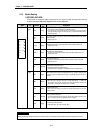
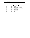
2) Initial Settings
(1) Available channel enabled : channel 0,
(2) Analog input : current input(DC 4 to 20 mA)
(3) Average processing setting : 10 times
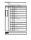
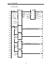
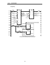
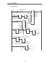
3) Descriptions of the Program
(1) %I0.0.0 turning On leads to the initial setting of A/D conversion module.
(2) %I0.0.1 turning On leads to displaying A/D conversion value on the BCD display.(%Q0.1.0 to %Q0.1.15)
(3) %I0.0.2 turning On leads to displaying error code of function block on the BCD display,
(%Q0.2.0 to %Q0.2.7)
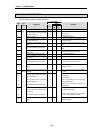
Initialize
%I0.0.0
Display error code with BCD
%I0.0. 1
%I0.0.2
Display A/D conversion
data with BCD
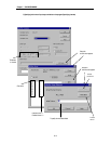
Digital BCD Display
(displaying error)
Channel 0 (4~20mA)
%Q0.2.0
~%Q0.2.7
Digital BCD Display
(displaying A/D conver-
sion value)
%Q0.1.0
~%Q0.1.15