


Operation
21
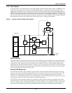
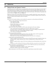
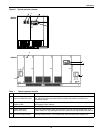
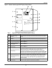
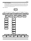
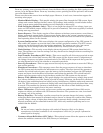
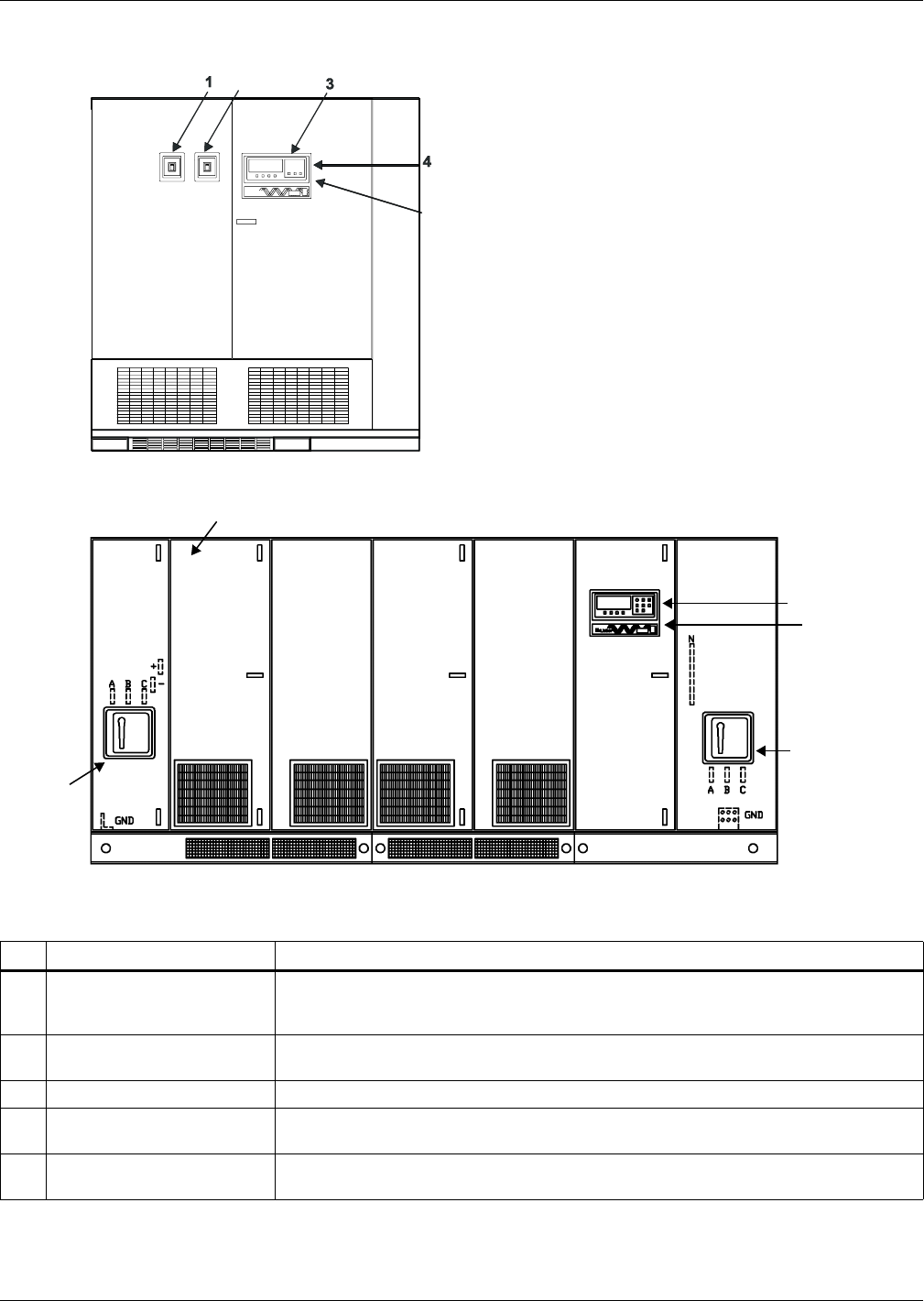
Figure 8 Typical operator controls
Table 1 Typical operator controls
Item Description Function
1 Input Circuit Breaker (CB1)
This manually operated circuit breaker provides power to the UPS module rectifier. In
625-750kVA modules and some 500kVA modules, this breaker is located in the
transformer cabinet.
2
Module Output Circuit
Breaker (CB2)
This manually operated circuit breaker connects the UPS module inverter output to the
UPS System Control Cabinet.
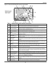
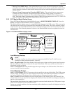
3 Operator Control Panel Refer to Figure 10 for controls available on this panel.
4
Control Disconnect
(behind inner door)
These two fuses provide power to the controls. They are normally closed (ON). Turn
Control Power OFF (by opening the two fuse holders) only for maintenance procedures.
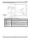
5
Interlock Button
(on rear of Control Panel)
Press this button to make authorized changes to any parameter protected by the
Security Access function. This includes time, date, auto-dial phone numbers, etc.
2
5
5
1000kVA
3
1
2
5
4
100kVA-
500kVA