


Operation
64
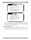
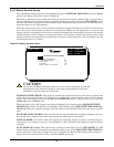
Load Block Messages
Status messages in the Load Block indicate how many modules are in the system, how many modules
are ON LINE and whether the system is operating in the redundant mode.
The following status messages may appear in the load block.
1. N OF X MODULES CONNECTED: The number N is the number of UPS modules ON LINE.
This means the module output circuit breaker is closed. X is the number of UPS modules in the
system (connected to this SCC). This number is set from the System Configuration screen.
2. REDUNDANT: The capacity of the UPS modules ON LINE is sufficient to supply the critical
load even if one module is taken OFF LINE. The critical load will remain on the UPS system if
one module goes OFF LINE.
3. NON-REDUNDANT: The critical load will be transferred to bypass if one module goes OFF
LINE and you must transfer the load to bypass in order to perform maintenance on any UPS
module.
4. TIME TO OVERLOAD TRANSFER: During an overload condition, the time remaining before
transfer (in seconds) is displayed at the bottom of the load block. At each Module (MMU), the
message is Time to Overload Shutdown.
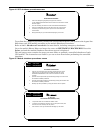
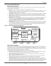
Alarm Messages
The alarm message area displays the alarm conditions that are present within the UPS system.
Alarm messages are displayed in flashing reverse video. During normal operation no alarm messages
should be present. Up to four messages are displayed. To see if any additional alarm conditions are
present in the UPS system, display the Present Status screen on the control panel.
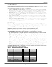
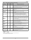
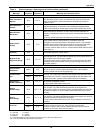
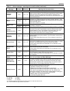
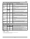
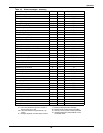
Table 9 is a complete list of all alarm messages and corrective actions, if any.
The first column lists the alarm message, with related alarms grouped together.
The third column indicates which special functions (if any) are initiated by the alarm.
D - The alarm initiates an auto-dial call through a user-provided modem to a remote terminal.
E - Message displayed only on Status Report screens including Event History.
F - The alarm freezes the History Status Report memory buffer in the cabinet where the alarm is
displayed. Pressing the Alarm Reset pad for more than 5 seconds will unfreeze the memory
buffer as long as the alarm is no longer active.
L - The alarm latches the displayed alarm message. Some alarm conditions are temporary (tran-
sient) and may not last long enough to be noticed. Latching the display (keeping it on) lets you
know that an alarm condition has occurred. A latching display alarm remains on the display
screen until the alarm condition is removed and the Alarm Reset pad is pressed.
R - The alarm is displayed on an (optional) Remote Monitor Panel. This information is also avail-
able for customer use through a set of contacts on a separate terminal board.
S - The alarm initiates a summary alarm at the Remote Monitor Panel and at the SCC.
The fourth column provides an explanation of the alarm condition, the critical bus status and the
corrective actions, if any, to remedy the alarm.
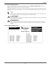
Table 8 Abbreviations used in alarm messages
Abbreviation Definition Abbreviation Definition
Auto Automatic Ov-temp Overtemperature
Avail Available O-volt Overvoltage
Batt Battery O-volts Overvoltage
Byp Bypass Ph Seq Phase Sequence
Cap Fuse Capacitor Fuse Rect Fuse Rectifier Fuse
Cont Power Control Power Rexfer Retransfer
Equip Equipment Shutdn Shutdown
H/W Hardware Static Sw Static Switch
Inv Fuse Inverter Fuse Un-volts undervoltage
OF/UF Over/Under Frequency Xfer Transfer