


User Manual
Hipulse - Single Phase ‘1+N’ UPS System 130 kVA - 110V
3
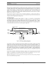
1.2.3 System Control Philosophy
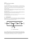
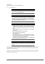
Normal Operation
During normal operation, i.e. when the UPS input supply is present and within
specification, both the rectifier and inverter sections are active and the static switch is
turned on to connect the inverter output to the critical load busbars. The battery
circuit breaker is also closed and the battery is therefore permanently float charged at
the d.c. busbar voltage level.
(1+N Parallel UPS System)
Note: As the unit outputs are connected in parallel, the System checks that the inverter control circuits
are perfectly synchronised with one another and with the Bypass Mains in terms of both frequency and
phase and that they have the same output voltages. Current supplied to the load is automatically
divided among UPSs. A warning message appears while synchronisation is in progress.
A module's static switch cannot close until these conditions are satisfied.
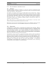
Mains Failure
If the power mains has a failure or is out of tolerance the rectifier will go off
automatically, while the Inverter will continue to operate on power from the battery for
a period of time which depends on the load and the capacity of the battery. If the
mains supply has not retuned within this time, the Inverter will go off automatically and
an alarm message will appear on the UPS operator control panel display.
Critical load will not be interrupted in the event of a drop or return of the AC power
mains.
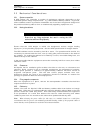
Return of power mains
When the mains return within the required tolerance, the Rectifier will start up again
automatically and gradually (power walk in), supplying power to the Inverter and
recharging the battery at the same time. There will be no interruption of the critical
load.
Off-Battery
If the battery system only is taken out of service for maintenance, it is disconnected
from the rectifier/ charger and inverters by means of (an) external disconnect
breaker(s). The UPS shall continue to function and meet all of the specified steady-
state performance criteria, except for the power outage back-up time capability.
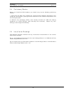
UPS Module fault
In the event of an Inverter fault, the Static Transfer Switch will automatically transfer
the load onto the Bypass Mains with no interruption. In such an event, request
qualified technical assistance.
(1+N Parallel UPS System)
In the event of a fault in a unit, the unit's Static Transfer Switch will automatically
exclude the unit from the system. If the system is still capable of providing the
required load, the remaining units will continue to supply the load with no interruption.
When the units still present in the system are no longer capable of fulfilling power
requirements, the load will automatically be transferred onto the MSS Bypass Mains.
The load will be transferred with no interruption if the Inverters are synchronised with
the network; if this is not the case, there will be an interruption lasting about 20
milliseconds.