


User Manual
Hipulse - Single Phase ‘1+N’ UPS System 130 kVA - 110V
56
1. If [OVERTEMPERATURE] or [OVERLOAD] alarm messages are active then (after allowing the
UPS to cool / checking that the load current on the Bypass line is not excessive) use the
procedure to carry out the reset (see Chapter 5 – Operating Instructions).
2. Check that the conditions for led(2) are satisfied.
3. Check that the Inverter led(8)- yellow – is OFF, otherwise follow Inverter switch ON procedure.
4. Check that no conditions exist which will prevent switching the INV ON (e.g. PC command).
5. Verify that condition leading to an emergency stop has not happened, in which case a Reset
must be carried out.
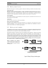
5. ON If this green led is OFF, then it signifies that the load has been transferred to the Static bypass supply. If
this is an automatic change over it will be accompanied by a fault warning on the display panel. Take the
appropriate actions for the display indication (see Display alarm message table 7-2).
6. OFF This led is mutually exclusive to led(5). If this amber led is ON, the load has been transferred to the
Bypass mains supply. Verify the cause by following the alarm indications at the LCD display panel. If the
above checks prove unsatisfactory then seek qualified assistance.
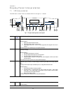
13. OFF This red led will flash ON and OFF and indicates that the UPS has detected fault, it will be accompanied by
a message on the display panel, take the required actions for the display panel message (see Display
alarm message table 7-2). This will be accompanied by an audible warning. Pressing the Alarm silence
switch (14) stops the audible alarm, but leaves the warning message displayed until the appropriate
condition is rectified.
16. OFF If this yellow led is ON it signifies that the battery voltage is low and that the end of battery discharge is
near. This will be accompanied by audible warning.
17. N/A This is a bargraph indicating the battery charge state and would normally have four or five of the leds ON.
When the unit runs on battery, this bargraph changes to give an indication of the time remaining on the
battery.
18. N/A This is a bargraph indicating the % of the total load that is being applied to the system.
19. OFF If this yellow led is ON it signifies that the applied load has exceeded the maximum. It will be
accompanied by all five load bargraph leds being ON (item 18), the Alarm warning indication flashing RED
(item 13) and an OVERLOAD messages on the visual display. This will be accompanied by an audible
warning. Reduce the load immediately.