


User Manual
Hipulse - Single Phase ‘1+N’ UPS System 130 kVA - 110V
27
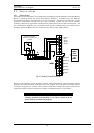
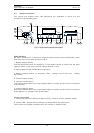
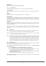
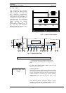
20. Emergency Stop - housed beneath a safety cover to prevent inadvertent
operation.
When the emergency stop switch is pressed it disables the static switch block entirely
(so removing load power). It also disables the rectifier and inverter, and trips the
battery circuit breaker. Under normal circumstances it does not remove UPS input
power since this applied through a manually controlled external isolator; however, if
the UPS input supply is connected via a circuit breaker having an electrical trip facility,
another section of emergency power off can be used to drive the external circuit
breaker’s trip.
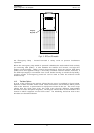
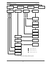
4.1.2 The Menu Options
A map of the routes to the options offered by the menu is provided in figure below.
Options include windows which show status information and windows which permit
data to be entered, or parameters for equipment control to be set. The menu map
shows that the route pass from the main menu through different intermediate
windows to reach the option targeted. The diagram shows each of the windows in the
format in which it appears on the LCD screen. The initializing, default & main menu
windows are described below.
............................................
............................................
............................................
............................................
............................................
............................................
............................................
............................................
............................................
............................................
............................................
............................................
............................................
............................................
............................................
............................................
............................................
............................................
............................................
............................................
............................................
............................................
............................................
............................................
............................................
............................................
............................................
............................................
............................................
............................................
............................................
............................................
............................................
............................................
............................................
............................................
............................................
............................................
............................................
............................................
............................................
............................................
............................................
............................................
............................................
............................................
............................................
............................................
............................................
............................................
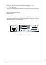
Emergency
Stop (EPO)
Fig 4 - 3: EPO on UPS module