


User Manual
Hipulse - Single Phase ‘1+N’ UPS System 130 kVA - 110V
21
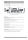
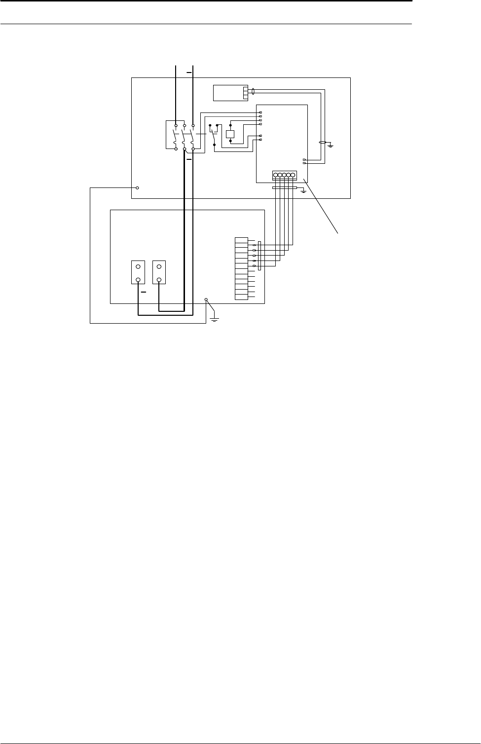
3.2.3 Emergency Stop
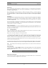
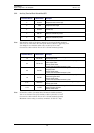
If an external Emergency Stop facility is required it is connected to terminals 5 & 6 of
the Auxiliary Terminal Block (X4) and connect the ‘normally closed’ remote stop switch
between these two terminals using shielded cable. If this facility is not used then
terminals 5 & 6 must be linked-out as shown in Figure 3-3.
Note: The Emergency Stop action within the UPS shuts down the rectifier, inverter and static bypass
and trips the battery circuit breaker. It does not however internally disconnect the input mains supply.
If required, this additional action can be facilitated by feeding the UPS input via a circuit breaker
which can be tripped by a second contact of the Emergency Stop switch.
Note: Terminals 11 and 12 of the Auxiliary Terminal Block (X4) are connected to a normally closed
contact of the UPS Display Panel Emergency Stop button and go open circuit when the button is
pressed. This output can be used as part of a wider Emergency Stop system to initiate an external
action (such as tripping an external supply breaker)
3.2.4 Back Feed Protection
Using an auxiliary terminal (pins 9-10 of connector X4) the UPS provides a normally
open contact to be used for opening of an external circuit protection device, to protect
the operator against back feed of energy resulting from a short-circuit fault of the
Bypass line SCRs. This auxiliary contact can be used, for example, in series with an
external low voltage source, in order to supply the trip coil of an automatic circuit
breaking device, located upstream of the UPS Bypass mains input. In the vent of
energy being backfeed the auxiliary circuit will activate closing the normally open
contact and as a result opening of the external circuit-breaking device; the UPS is
disconnected from the Bypass mains supply. The electrical characteristics of the
auxiliary contact are 50V (a.c. or d.c.) @ 1 Amp.
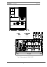
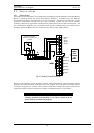
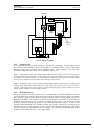
Fig 3-3: Battery Connection
3
2
1
V<
+
1
2
3
4
5
6
7
8
9
10
11
12
X3
UPS CABINET
BATTERY
CIRCUIT
BREAKER
X3
X4
X5
X6
X7
X8
X9
X2
X10
1 2 3 4 5
X1
Sensor
Temperature
(Optional)
Battery C.B.
Controller
+
To Battery
+