


User Manual
Hipulse - Single Phase ‘1+N’ UPS System 130 kVA - 110V
19
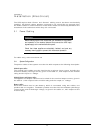
3.2 Control cables
3.2.1 Battery Control
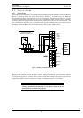
The battery circuit breaker is controlled by the Battery Circuit Breaker Controller Board
which is located within the Input Transformer Cubicle - or adjacent to the Battery
Circuit Breaker when the batteries are rack-mounted. This board controls the circuit
breaker’s undervolts release coil and also provides a path for the circuit breaker
auxiliary contacts to signal the circuit breaker status back to the UPS control logic. All
the connections between the controller board and the UPS module are made via the
Auxiliary Terminal Block which is located in the base of the UPS cabinet.
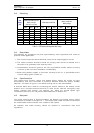
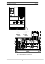
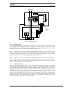
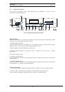
Connect the battery circuit breaker control and temperature compensation cables
between the UPS auxiliary terminal block and battery circuit breaker controller board
as shown in figure 3-3. These cable must be shielded, shield should be connected at
protective earth of Input transformer cubicle or battery breaker, not of UPS.
CAUTION
If battery temperature compensation is not used the system must be
de-activated by commissioning engineer.
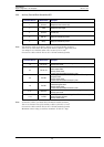
Fig 3-2 : Auxiliary Terminal Block detail
1 2 3 4 5
B A T T E R Y C I R C U I T
B R E A K E R C O N T R O L L E R
B O A R D
X1
1
2
3
4
5
6
7
8
9
10
11
12
X3
1
2
3
4
5
6
7
8
9
10
11
12
X4
LINKS
Ext OFF Inv.
Ext Sw. Out
Ext EPO
Ext BYP
Back feed
Int EPO
Common
I batt.
Common
Batt. Sw.
Batt. trip
AUXILIARY
TERMINAL
BLOCK
LOCATED IN
UPS
CABINET