


User Manual
Hipulse - Single Phase ‘1+N’ UPS System 130 kVA - 110V
55
CHAPTER 7
Display Panel Interpretation
7.1 LED Interpretation:
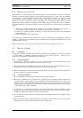
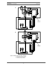
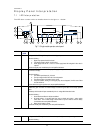
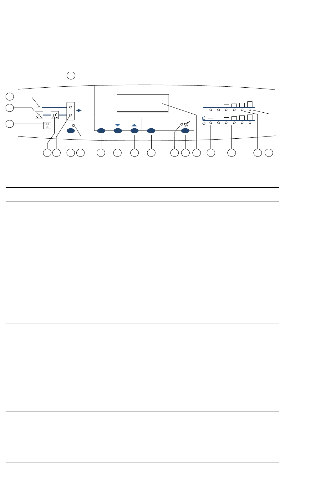
The LED item number refers to details shown in the figure 7.1 below.
LED N0.
NORMAL
STATE
INTERPRETATION – ACTION
1. ON If this green led is OFF, it signifies a problem with the Bypass input a.c.
Check the following –
1. Bypass input power switch Q2 is closed.
2. Input Supply voltage is within 10% of nominal
3. Power supply fuses are OK – on the a.c. Power supply board will extinguish if either fuse is
ruptured.
If the above checks prove unsatisfactory then seek qualified assistance.
2. ON If this led is OFF, a problem exists in the Input power supply or in a part of the rectifier. An alarm message
is visible at the display.
Check the following –
1. The rectifier input isolator (Q1) is closed.
2. The input voltage is within the limits of normal operation.
3. The phase sequence of the mains input is correct.
4. Verify that condition leading to an emergency stop has not happened, in which case a Reset
must be carried out.
If these checks do not give a positive result, request qualified assistance.
3. OFF If this yellow led is ON it signifies that the battery is not available. This could be due to the battery circuit
breaker being open or that the d.c. busbar voltage is below the figures stated in the item(2) specified
above.
The battery circuit breaker will open automatically if the d.c. voltage falls below these levels.
Check the following –
1. Check that the conditions for led(2) are satisfied.
2. DC busbar voltage – if not above 320V, then carry out checks as for led(2) – mains rectifier
failure above. If d.c. busbar voltage is above 320V but you are unable to close the battery
circuit breaker then seek qualified assistance.
3. Battery circuit breaker is closed.
If the above checks prove unsatisfactory, then seek qualified assistance.
4. ON If this green led is OFF, it signifies that the inverter is not producing its correct output voltage.
Check the following –
Fig 7-1: Single module operator control panel
ESC
MENU
ENTER
INV
%
DISPLAY
1
2
3
7 8 9 10 11 12 13 14 15 16 17 18 194 5
6