


Single Module UPS Installation
8
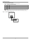
1.6 Power Cables
The cable design must comply with the voltages and currents provided in this section, follow local wir-
ing practices and take into consideration the environmental conditions (temperature and physical
support media).
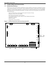
For cable entry terminal, refer to Figure 22.
!
WARNING
Before starting the UPS, ensure that you are aware of the location and operation of the
external isolators that connect the ups input/bypass supply to the mains distribution panel.
Check that these supplies are electrically isolated and post any necessary warning signs to
prevent their inadvertent operation.
!
WARNING
Failure to follow adequate earthing procedures may result in electromagnetic interference or
in hazards involving electric shock and fire.
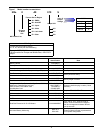
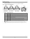
Table 1 Maximum steady state AC and DC currents
UPS
Rating
(kVA)
Nominal Current, Amps Busbar Stud Size
Input Mains Current
1,2
With Full Battery
Recharge
3ph + N
Output Current
2
at Full Load
3ph + N
Battery at
End of
Discharge
Input/Output/
Bypass
Cables
External
battery
Cables
(Bolts)
Torque
Load
(Nm) 380V 400V 415V 380V 400V 415V Bolt
Hole
Dia.
(mm)
10 22 21 20 15 14 13 22
M6 6 M6 5
15 33 32 31 22 21 20 33
20 44 43 42 30 29 28 44
30 63 62 61 45 44 42 66
1. Input mains current listed for common rectifier and bypass AC input. For split input the rectifier current is 94% of the currents
listed.
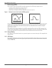
2. Non-linear loads (switch mode power supplies) affect the design of the output and bypass neutral cables. The current
circulating in the neutral cable may exceed the nominal phase current. A typical value is 1.5 In.
3. Protective earth cable: Connect each cabinet to the main ground system must follow the most direct route possible.
The earth conductor shall be sized in accordance with the AC supply fault rating, cable lengths and type of protection. Typical
cross sectional areas are 2.5mm
2
(10kVA), 6mm
2
(15kVA), 10mm
2
(20kVA), 16mm2 (30kVA), as per AS / IEC 60950-1
4. When sizing battery cables, a maximum volt drop of 4 VDC is permissible at the current ratings given in Table 1. The load
equipment is generally connected to a distribution board containing individually protected busbars rather than connected
directly to the UPS output. The output cables from paralleled units to the parallel distribution bus should be of same length so
as to optimise the sharing of current. Do not form coils, so as to minimise the formation of electromagnetic interference.
5. For terminal location – refer to 4.0 - Installation Drawings)
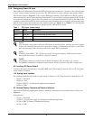
Table 2 Distance from floor to connection point on the equipment
UPS
Minimum Distance
mm (in.)
Rectifier A.C. Input supply 284 (11-1/5)
Bypass A.C. Input supply 284 (11-1/5)
UPS Output A.C. 369 (14-1/2)
Battery Power 369 (14-1/2)
Auxiliary cables: Monitor board (U2) 1104 (43-1/2)