


Operating Procedures
52
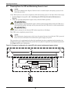
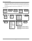
6.12 Isolating One Module in a Multi-Module System
1. With all UPS modules in the system in Normal mode, open the external output isolator.
2. Press the UPS EPO to isolate the batteries.
3. Open the UPS door to gain access to the main power switches SW1 and CB1.
4. Turn the rotary switch (SW1) to the Bypass position then continue to rotate to Test.
5. Open rectifier input breaker CB1.
NOTE
The Multi-Module system must have at least one UPS module redundant in the system and
have an external output breaker installed with interlocking cables connected to the UPS
module. The inverter firmware in each UPS in the system must be I140 or greater.
NOTE
Opening the external output isolator under these condtions puts the UPS module into Standby
mode. This is indicated by a flashing inverter LED and the message “Check UPS output.”
An “Inverter asynchronous” alarm is also normal. The remaining UPS modules will remain on
line and “Parallel comm fail” will annunciate.
NOTE
With the UPS external output breaker open and auxiliary switches closed the UPS control will
enable the UPS switch to be rotated through “Bypass” without initiating the remaining on line
UPS modules to transfer to Bypass.
!
WARNING
Hazardous Battery Voltage
No operator serviceable parts are located behind covers that require a tool for their removal.
Only qualified service personnel are authorised to remove such covers.
The UPS battery and connecting terminals remains energized at hazardous voltage levels at
all times. The battery is located behind protective covers that require a tool for their removal:
inside the UPS cabinet, inside a free-standing battery cabinet or on open racks inside a
dedicated battery room that may be locked.