


UPS Multi-Module Installation
29
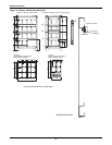
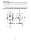
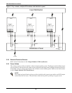
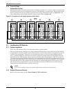
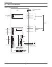
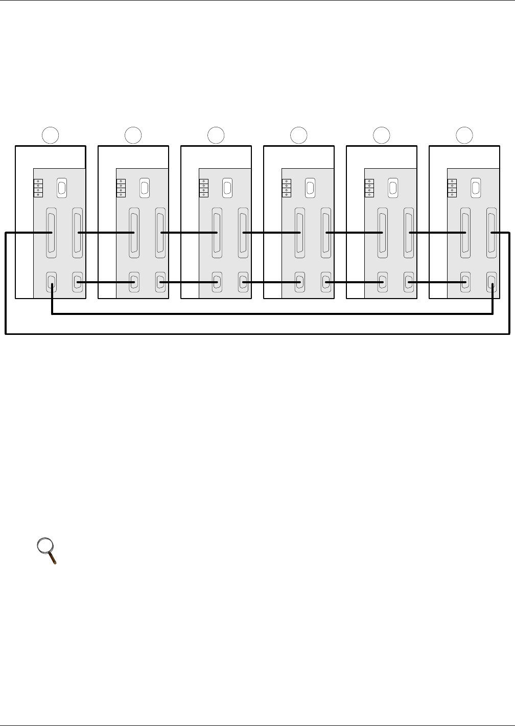
3.2.4 Control Cables
Intermodule Control
Shielded and double insulated control cables available in lengths of 5, 10 and 15 meters must be must
be interconnected in a ring configuration between UPS modules as shown below. The parallel control
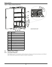
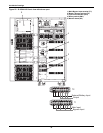
board is mounted on the top, behind protective cover of each UPS module (refer to Figure 23). The
ring configuration ensures high reliability of the control. Refer to Figure 16.
Figure 16 Connection of 1+N system parallel control cables
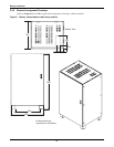
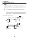
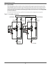
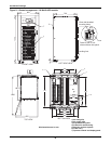
3.3 Hot-Standby UPS Modules
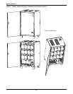
3.3.1 Cabinet Installation
Place the UPS modules side by side and interconnect as shown below.
The hot standby mode comprises two series connected UPS modules of the same rating. One module
is designated as the hot standby master (downstream), and the other module is designated as the hot
standby slave (upstream). Their roles are determined by power connection and configuration soft-
ware. In normal operation, both slave and master operate in normal mode and the output from one
upstream (slave) UPS feeds the bypass input to the other (downstream/master) UPS. The output of
the downstream (master) UPS is connected to the critical load and is always synchronised to the out-
put of the upstream (slave) UPS. If the inverter of the UPS connected to the load fails, the inverter of
the upstream (slave) UPS supplies the load through the downstream (master) UPS bypass circuit.
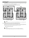
The system can be programmed to cycle the downstream (master) UPS between normal mode and
bypass mode so that both ups are equally exercised.
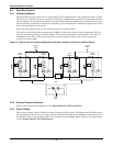
3.3.2 External Protective Devices
Refer to the instructions in 1.0 - Single Module UPS Installation.
NOTE
If it is a hot-standby system, the master (downstream) must be turned on first.
X1-1 X1-2
X2-2 X2-1
Parallel Board
X4
X3
P5
P3
P4 P1
P2
X1-1 X1-2
X2-2 X2-1
Parallel Board
X4
X3
P5
P3
P4 P1
P2
X1-1 X1-2
X2-2 X2-1
Parallel Board
X4
X3
P5
P3
P4 P1
P2
X1-1 X1-2
X2-2 X2-1
Parallel Board
X4
X3
P5
P3
P4 P1
P2
X1-1 X1-2
X2-2 X2-1
Parallel Board
X4
X3
P5
P3
P4 P1
P2
X1-1 X1-2
X2-2 X2-1
Parallel Board
X4
X3
P5
P3
P4 P1
P2
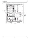
1 2 3 4 5 6
UPS