


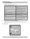
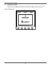

Operator Control Panel and Display
62
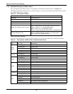
Unit Over load Timeout
The UPS is confirmed to overload and the overload times out.
Note 1: the highest loaded phase will indicate overload timing-out first.
Note 2: When the timer is active then alarm “unit overload” should also be active as the load is
above nominal.
Note 3: When the timer has expired, the inverter Static Switch is opened and the load
transferred to bypass. The inverter shutdown and will restart after 10 seconds.
Note 4: If the load decreases lower than 95% after 5 minutes, the system will transfer back to
inverter mode.
Confirm that the alarm is genuine by checking the load percent indicated on the LCD. If an
overload is indicated then check the load, and investigate any additional load connected prior to
the alarm (if applicable).
Byp. Abnormal Shutdown Both bypass and inverter voltages unavailable. Load interruption
Inverter Over Current Inverter Pulse Width Modulation module overloaded.
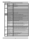
Bypass Phase Reversed
The phase sequence direction of bypass voltage is reversed.
Normally, the phase of phase B lags 120 degrees behind phase A, and the phase of phase C
lags 120 degrees behind phase B.
Verify that the phase rotation of the bypass supply presented to the UPS is correct, and rectify it
if it is found to be in error
Load Impact Transfer
A transfer to bypass occurred due to a large step load. The UPS should recover automatically.
Turn on connected equipment in sequential order to reduce the step loading of the inverter.
Transfer Time-out
The load is on bypass power due to excessive number of transfers that occurred within the last
hour.
The UPS will recover automatically and will transfer the load back to inverter power within an
hour.
Load Sharing Fault UPS modules within a parallel system are not sharing the load current equally.
DC Bus Abnormal DC input voltage to inverter beyond limits. Inverter shuts down. Load transfers to bypass.
System Transfer
The whole paralleled UPS system transferred to bypass at the same time. This message will
appear on the UPS which passive transfer to bypass
Parallel Board Fault
Malfunction of the paralleling control circuits of this UPS module. Can cause “System Transfer”
to bypass.
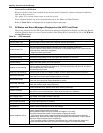
DC Bus Over Voltage
Rectifier, inverter and battery converter were shutdown because DC bus voltage is too high.
Check whether there is a fault in rectifier side. If no, then check whether overload occurs.
Restart the inverter after resetting the fault
Parallel Connect Fault
The parallel cables are not connected correctly in a parallel system.
Reset the fault by pressing the “fault clear” button, then restart the inverter by pressing the
“inverter on” button.
Bypass Over Current Bypass current is over limit above 135% rating. The UPS just alarms and does nothing.
LBS Active
Load Bus Synchronisation is active. The UPS is acting as an LBS master or slave in a dual bus
configuration.
Setting Save Error History records not saved. (Reserved)
Mains Neutral Lost AC Input mains reference neutral not detected.
Protocol version clash Firmware incompatibility between Monitor Board and Digital Signal Processor Board.
Battery ground fault Battery leakage to ground detected (option)
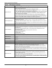
Inv. Turned On Manually Manual Turn On via front panel
Inv. Turned Off Manually Manual Turn Off via front panel
EPO Emergency Power Off direct access key pressed or external command received
Transfer Confirm
Prompt to press “enter” key to acknowledge that an interrupted load transfer to bypass will
happen.
Transfer Cancel Prompt to press “ESC” key to avoid that an interrupted load transfer to bypass will happen.
Unit Off Confirm
Prompt to press “enter” key to acknowledge that the UPS will be disconnected from other
paralleled UPS modules.
System Off Confirm
Prompt to press “enter” key to acknowledge that the all paralleled UPS will be disconnected
from the load.
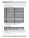
Table 22 UPS messages (continued)
Message Description / Suggested Action (if any)