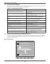
Operator Control Panel and Display
60
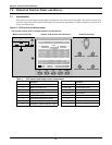
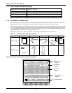
Current Record Window
Keeps a log the events that resulted in the current mode of operation. Ignores transient conditions
that have been resolved.
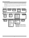
Use “page” (F1) and up / down arrow to read the events.
For a complete history log, refer to the Records tab of the Menu and Data Window.
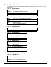
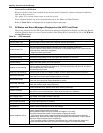
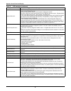
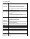
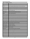
Refer to Table 22 for a complete list of supported status messages.
7.2 All Status and Event Messages Displayed on the UPS Front Panel
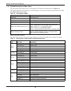
This is the complete list of UPS events and status messages supported for display in either the Record
window (Historic data) or in the Current window (Prevailing data) as described in 7.1.4 - LCD Moni-
tor and Menu keys.
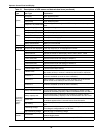
Table 22 UPS messages
Message Description / Suggested Action (if any)
Inverter Comm. Fail Internal RS485 communication failure between monitor and inverter
Rectifier Comm. Fail Internal RS485 communication failure between monitor and rectifier
Parallel Comm. Fail
The CAN communication between different UPSs within a parallel system fails.
1.Check if there are some UPSs not powered on in the parallel system. If so, power on these
UPSs and check if the alarm disappears.
2. Press Fault Clear push button.
Battery Overtemp. The Battery temperature is over limit. Check the battery temperature and ventilation
Ambient Overtemp. The Ambient temperature is over limit. Check the ventilation of UPS room.
Battery Fault Battery detected faulty (Reserved)
Replace Battery Battery test failed, Battery should be replaced.
Battery Low Pre-warning
Before the end of discharge, battery undervoltage pre-warning should occur. After this pre-
warning, battery should have the capacity for 3 minutes discharging with full load. The time is
user-configured from 3 to 60 minutes.
Shut down the load in time.
Battery End of Discharge Inverter turned off due to low battery voltage. Check the utility failure and try to recover it.
Mains Volt. Abnormal
Mains Voltage exceeds the upper or lower limit and results in rectifier shutdown.
Check the input line-to-neutral voltage amplitude of rectifier.
Mains Undervoltage
Mains Voltage is undervoltage with derated load.
Check the input line-to-line voltage amplitude of rectifier
Mains Freq. Abnormal
Mains frequency is out of limit range and results in rectifier shutdown.
Check the rectifier’s input voltage frequency
Rectifier Fault Rectifier detected faulty. Rectifier shuts down. Battery discharges.
Rectifier Overtemp.
The temperature of heat sink is too high to keep the rectifier running.
The UPS can recover automatically. Check the environment and ventilation.
Batt. Contactor Fail Battery contactor or circuit breaker not responding to control signals.
Batt. Charger Fault The voltage of the battery charger is too high.
Control Power 1 Fail UPS operates but Redundant Control Power is not available.
Mains Phase Reversed AC Input phase sequence is reversed.
Rectifier Overcurrent Rectifier is overloaded.
Soft Start Fail Rectifier could not start due to low DC bus voltage
Bypass Unable to Trace
This alarm is triggered by an inverter software routine when the amplitude or frequency of
bypass voltage is beyond the normal range.
The amplitude threshold is fixed for positive and negative 10% rating.
This alarm automatically resets once the bypass voltage goes normal.
1. First verify that the bypass voltage and frequency displayed on the panel is within the
selected range. Note here the rated voltage and frequency are specified by “Output voltage
level” and “Output frequency level” respectively.
2. If the displayed voltage is believed to be abnormal, then verify the bypass voltage and
frequency presented to the UPS. Check the external supply if it is found to be faulty.


