


Options—For Assembly Inside the UPS Cabinet
67
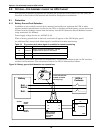
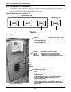
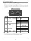
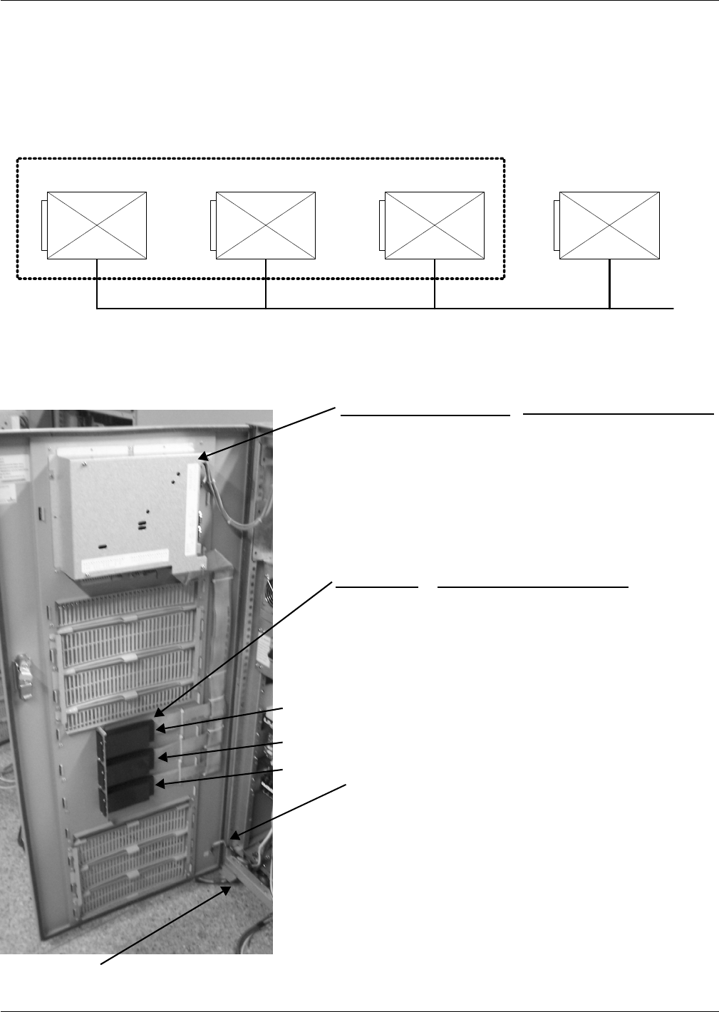
8.1.2 Redundant Fan for Power Module
In addition, to ensure sufficient cooling power at various operation modes with 100% rated load, a
redundant power module fan set can be supplied, thus ensuring continuity of UPS operation even
with the failure of some fans. No extra footprint is required.
Figure 37 Redundant power module fan set
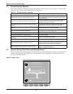
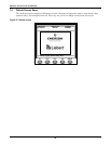
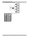
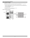
Figure 38 Communication bays and cable location
Fan120 Fan120Fan120Fan120
(AC Fan 1-4)(AC Fan 1-3)(AC Fan 1-2)(AC Fan 1-1)
Redundant AC Fan
TOP VIEW
Standard AC Fan
Notes:
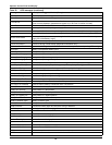
a) All Intellislot cards are supported in any bay.
b) Port sharing is:
- PERMITTED between RS232-x DB9 devices and Relay /
Multiport4 Intellislot cards (i.e., Serial Multilink software
will work from RS232-1 DB9 also when relay card is
inserted in the top bay.
- NOT PERMITTED between RS-232-x D-B9 devices and
OCWeb / OC485 cards (i.e., Serial MultiLink software will
not work from RS232-1 DB-9 when OCWeb card is inserted
in the top bay.
RS-232-1 DB-9 (COM Port 1) - Serial MultiLink Software
(Port Setting 2400 Baud)
RS-232-2 DB-9 (COM Port 2 - Service Access Software
(Port Setting 9600 Baud)
Top Bay
Mid Bay
Bottom Bay
Relay Card (no port setting required)
Multiport4 (no port setting required)
OCWeb LB / OC485 (port setting 2400 Baud)
Suggested routing of customer-supplied
communication cables
Gland plate for cable exit
DB-9
Monitor
Board
Top
Mid
Preferred Device This LocationLocation
Bottom
Location
Preferred Device This Location