Operator Control Panel and Display
57
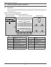
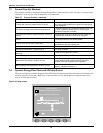
The function of keys F1 to F4 is shown by a self-explanatory icon as appropriate for the particular
window. As shown in Figure 32 above, pressing F1 moves the cursor (resting in “OUTPUT”) from the
UPS Menu Window (2) to current record window (4) where it would first rest in “Input breaker closed’.
In a similar manner, pressing F2 would move the cursor from the Output data window to the Bypass
data window.
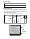
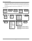
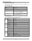
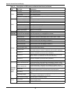
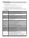
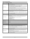
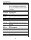
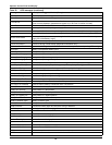
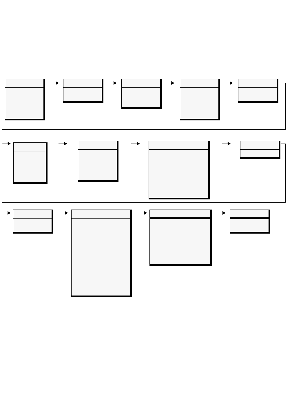
The summary menu tree is shown below. Refer to 7.2 - All Status and Event Messages Displayed
on the UPS Front Panel for a detailed description of each menu item.
Figure 33 Menu tree
Battery
Battery voltage (V)
Battery current (A)
Battery temperature (°C)
Remain Time Min.
Battery capacity (%)
Battery boost charging
Battery float charging
Battery disconnected
Command
Battery maintenance test
Battery capacity test
System test
Stop testing
Freshening Charge
Stop Freshening
Charge
Version
UPS version
UPS model
Settings
Display contrast
Date format set
Date & time
Comm1 baud rate
Comm2 baud rate
Comm3 baud rate
Communication address
Communication mode
Callback times
Phone No.1
Phone No.2
Phone No.3
Command password
System
Sout (kVA)
Pout (kW)
Qout (kVAR)
Single unit, no
parallel data
Records
(history log)
Language
(Choices for
display)
Mains (input)
L-N voltage (V)
L-N current (A)
Frequency (Hz)
L-L voltage (V)
Power factor
Load
Sout (kVA)
Pout (kW)
Qout (kVAR)
Loadlevel %
Crest factor
Bypass
L-N voltage (V)
Frequency (Hz)
L-L voltage (V)
Output
L-N voltage (V)
L-N current (A)
Frequency (Hz)
L-L voltage (V)
Power factor
TX Input *
L-N voltage (V)
L-L voltage (V)
* When configured, input transformer voltages are
displayed on the front LCD. When not activated, the
values are hidden.
** When configured, output transformer voltages are
displayed on the front LCD. When not activated, the
values are hidden.
TX Output **
L-N voltage (V)
L-L voltage (V)


