Battery Installation
19
2.3 Battery Cabinet
2.3.1 Introduction
This cabinet can also be used in conjunction additional cabinets, to provide the necessary accommoda-
tion required by the larger cells associated with system’s having a long autonomy time.
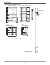
Where two (or more) cabinets are used they are positioned alongside each other and secured and
bonded together. If the cabinet(s) is located immediately adjacent to the main UPS equipment the two
units are bolted together.
2.3.2 Temperature Considerations
Valve-regulated, lead acid battery cells are sensitive to ambient temperature and should be operated
between 15°C and 25°C (59-77°F). Battery capacity is increased by 1% for every 1°C (2°F) increase in
temperature up to 25°C (77°F). Battery life is reduced at temperatures above 25°C (77°F).
When batteries are mounted in the same room as the UPS unit, it is the battery that dictates the
designed maximum ambient temperature, not the UPS. — i.e. in the case of valve-regulated cells, the
ambient room temperature should be kept between 15°C and 25°C (59-77°F), and not between 0°C
and 40°C (32-104°F) (which is the specified main equipment operating temperature range). Tempera-
ture deviations are permissible for short periods, provided the average temperature does not exceed
25°C (77°F).
2.3.3 Dimensions
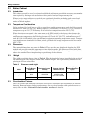
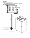
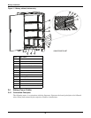
The external dimensions are shown in Table 8. These are the same height and depth as the UPS
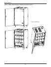
module and provide a matching appearance when bolted together. All cabinets are fitted with doors,
which must be fully opened in order to fit or remove the batteries. The door swing must therefore be
taken into consideration when planning the positioning of the cabinets.
2.3.4 Weight
The unladen weight is shown below in Table 8. When designing the battery installation the weight of
the batteries and cables must be added to the unladen weight. This is particularly important when
placing the NX on a raised floor.
2.3.5 Circuit Isolator Features
The UPS is fitted with Anderson connectors and fuses for connection and disconnection of internal
batteries. External battery banks require battery fuses or circuit breaker (with optional status con-
tacts). Refer to 1.8.3 - External Circuit-Breaker Interface for details.
Table 8 Dimensions and weight
Model
Optional
Circuit Breaker
Amperes
Maximum
Discharge Current
(at EOD)
External Cabinet
WxDxH mm (in)
Cabinet Weight
Without Batteries
kg (lb)
Battery Cabinet
50A
10kVA 22A
15kVA 33A
20kVA 44A
820x700x1400
(32-1/4x27-5/8x55)
170 (375)
80A 30kVA 66A


