Operation
43
5.3.4 Bypass Mode
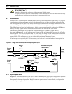
If the inverter overload capacity is exceeded, or if the inverter becomes unavailable for any reason,
the static transfer switch will perform a transfer of the load from the inverter to the bypass source,
with no interruption in power to the critical AC load. Should the inverter be asynchronous with the
bypass, the static switch will perform a transfer of the load from the inverter to the bypass with inter-
ruption in power to critical AC load. This is to avoid paralleling of unsynchronised AC sources. This
interruption is programmable but typically set to be less than 3/4 of an electrical cycle, e.g., less than
15ms (50Hz) or less than 12.5ms (60Hz).
5.3.5 Maintenance Mode (Manual Bypass)
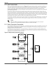
A manual bypass switch is available to ensure continuity of supply to the critical load when the UPS
becomes unavailable e.g. during a maintenance procedure. This manual bypass switch is fitted in all
UPS modules and rated for full load of one module.
5.3.6 ECO Mode (Single UPS Only)
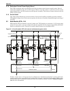
IF ECO mode is selected, the double-conversion UPS operation is inhibited at most times for the pur-
pose of saving energy. In this mode of operation, not unlike UPS of line-interactive or stand-by tech-
nology, the bypass is the preferred source and only when the voltage and / or frequency of the bypass
supply are beyond pre-defined and adjustable limits the critical AC load is transferred to the inverter.
This transfer takes place with an interruption of less than 3/4 of an electrical cycle, e.g., less than
15ms (50Hz) or less than 12.5ms (60Hz).
5.3.7 Parallel Redundancy Mode (System Expansion)
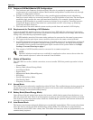
For higher capacity or higher reliability or both, the outputs of up to six UPS modules can pro-
grammed for directly paralleling while a built-in parallel controller in each UPS ensures automatic
load sharing.
5.3.8 Hot-Standby Mode
This is an alternative 1+1 redundancy application that ensures higher availability or better usage
control or both. Two UPS are connected in Hot Stand By mode as follows: UPS 1connects to the criti-
cal load, and UPS 2 connects to the bypass of UPS 1. The remaining AC inputs are connected to the
incoming AC mains supply. UPS 1 synchronises to the output of the UPS 2 ensuring uninterrupted
load transfer from UPS 1 to UPS 2 or vice versa. This ensures that any specified load is supplied by a
UPS while still providing a bypass path to cater for overloads. Further, the system can also be pro-
grammed to reverse UPS1 between Normal and Bypass Modes so that each UPS is equally utilised.
This interval is programmable from 1 to 4,320 hours (180 days).
5.3.9 Frequency Converter Mode
The NX UPS can be programmed into frequency converter mode for either 50Hz or 60Hz stable out-
put frequency. The input frequency may vary from 40Hz to 70Hz. In this mode the static bypass oper-
ation is disabled, and the battery becomes optional depending on any requirement to operate in
battery mode (stored energy mode).


